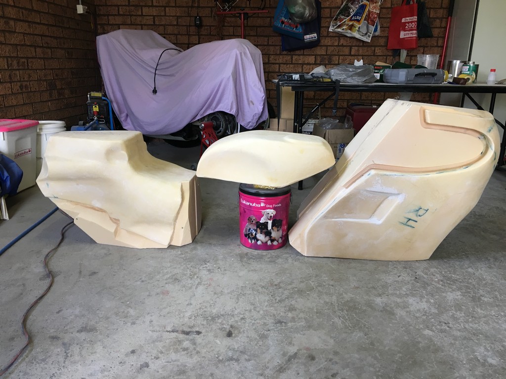
The FWS1000’s styling (fairing, fuel tank, seat etc.) is to a large extent what forms its identity. From a distance it looks typical of a racing motorcycle of the era. A closer examination of the detail of the FWS’ bodywork reveals how much of its form was dictated by function.
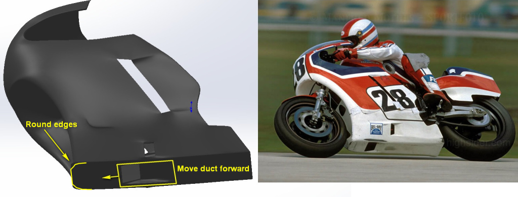
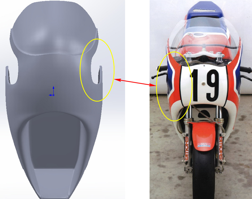
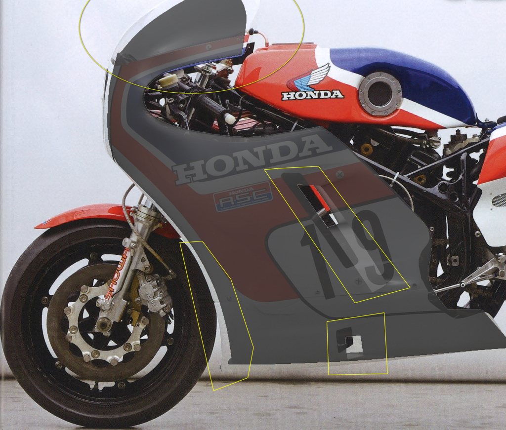
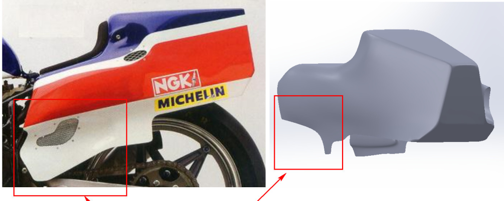
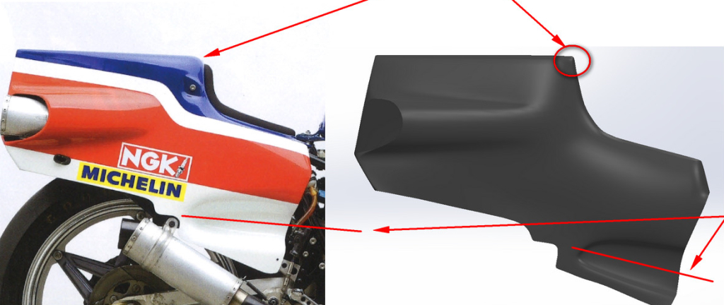
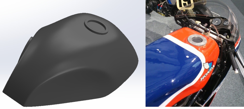
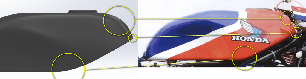
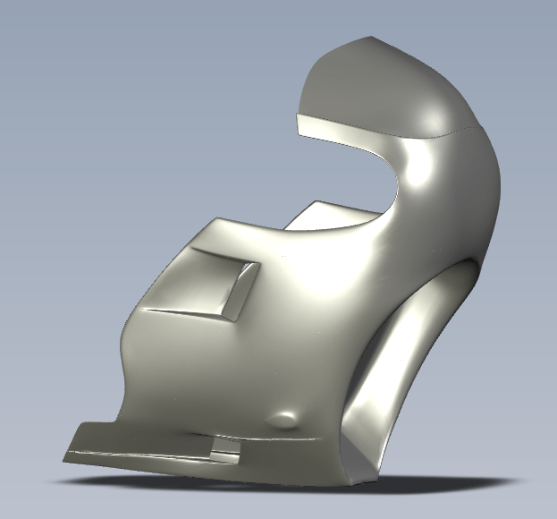
The snub nosed fairing is narrow and hugs the chassis as allowed by the slim V4 engine layout. The front duct is open only for the inverted ‘U’ shaped radiator, an oil cooler in the chin and a small access hole in the centre panel. The radiator exhaust ducting on each side is asymmetrical for reasons unknown to me. The front of the fuel tank is broad and hunched over the triple clamps. Its lines taper rearwards to a narrow finish allowing the rider plenty of room. The seat unit features scalloped and bulbous side panels, cooling vents and a muffler outlet on the right hand side to accommodate the snaking pipes of the rear cylinder bank exhaust system. The process of designing and manufacturing the bodywork parts we undertook was as follows.

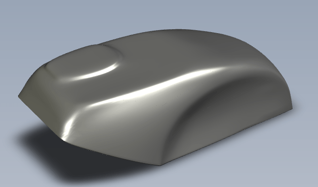
Bodywork parts CAD modelling
Replicating these forms was difficult. There are no off the shelf panels or existing donor parts that looked similar enough to warrant modificaton to suit so we had to start from a clean sheet. The methodology we adopted to model these body parts was to gather as many images of the FWS1000 as possible from as many angles and perspectives as possible and use the images as references for the 3D animation software.
Once modelled to a level of visual compatability the models were imported into CAD software for the creation of surfaces that a CAM package can use for subsequent CNC machining. Scaling and refining the details of the models was a very time consuming process. The end result mightn’t be 100% accurate but it’s pretty close.


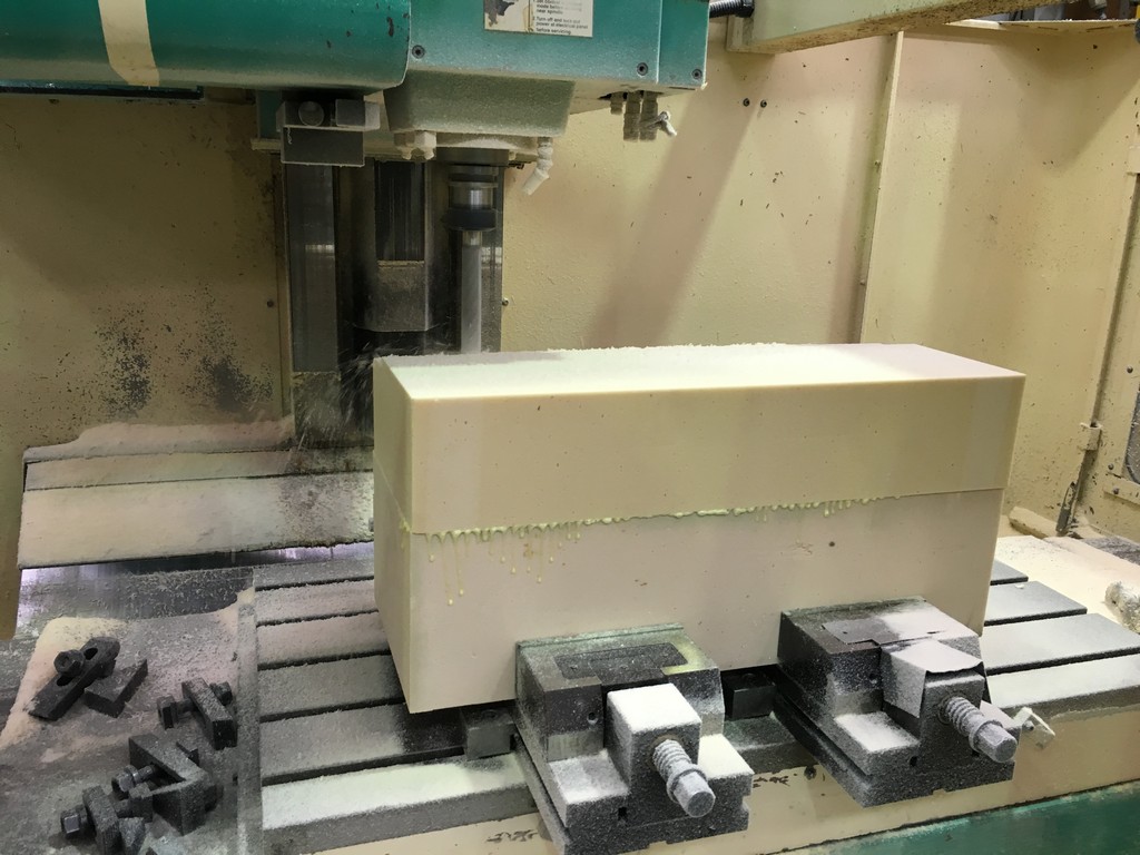
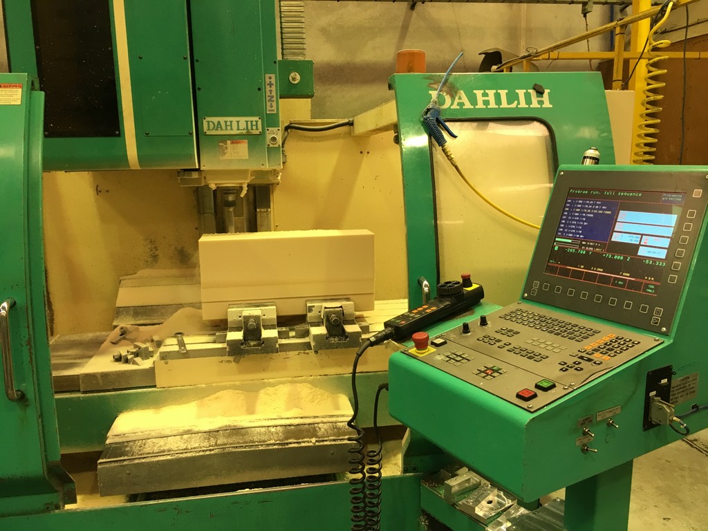
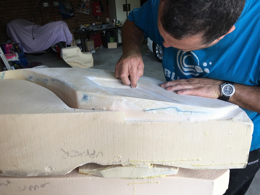
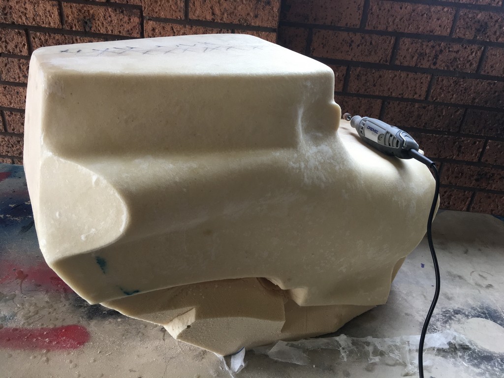
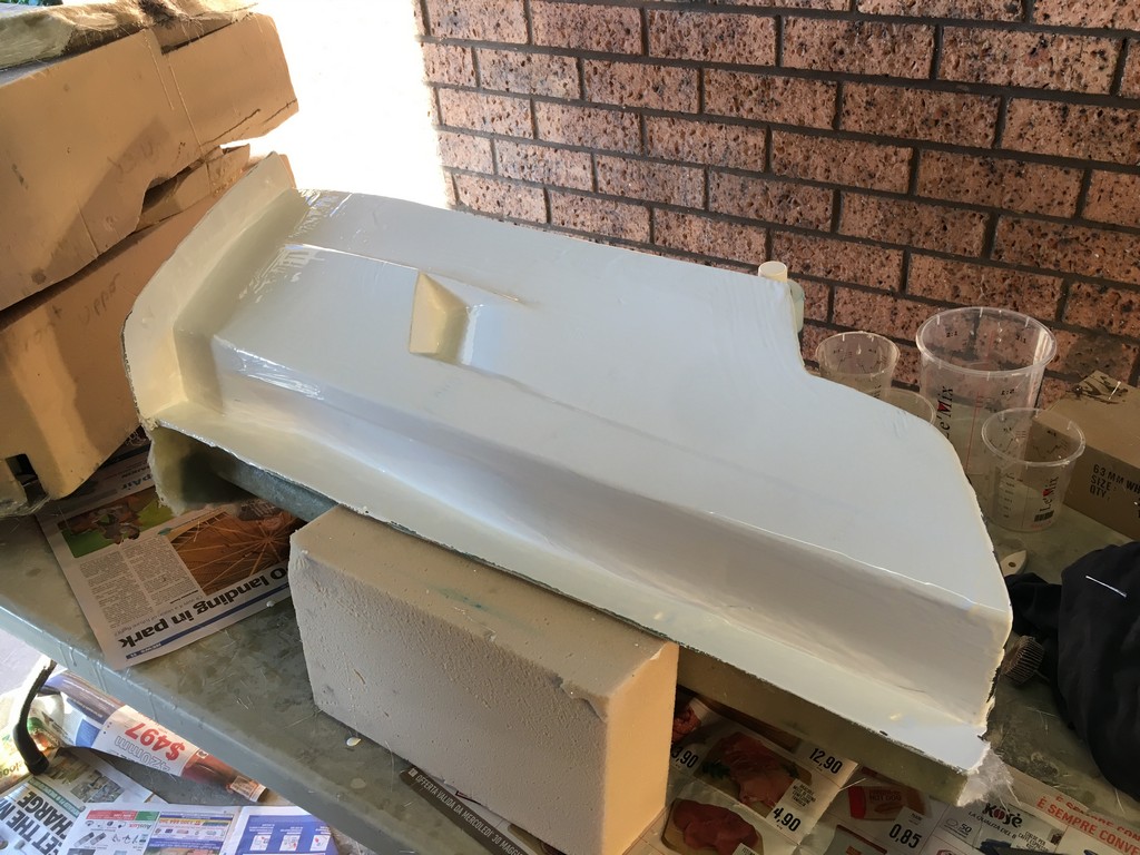
Manufacturing the foam plugs
Once the modelling was complete the next step in the process involved machining physical plugs of the CAD models from rigid urethane foam. Foam blocks were set up in a CNC machining centre and carved out as per the CAD design.


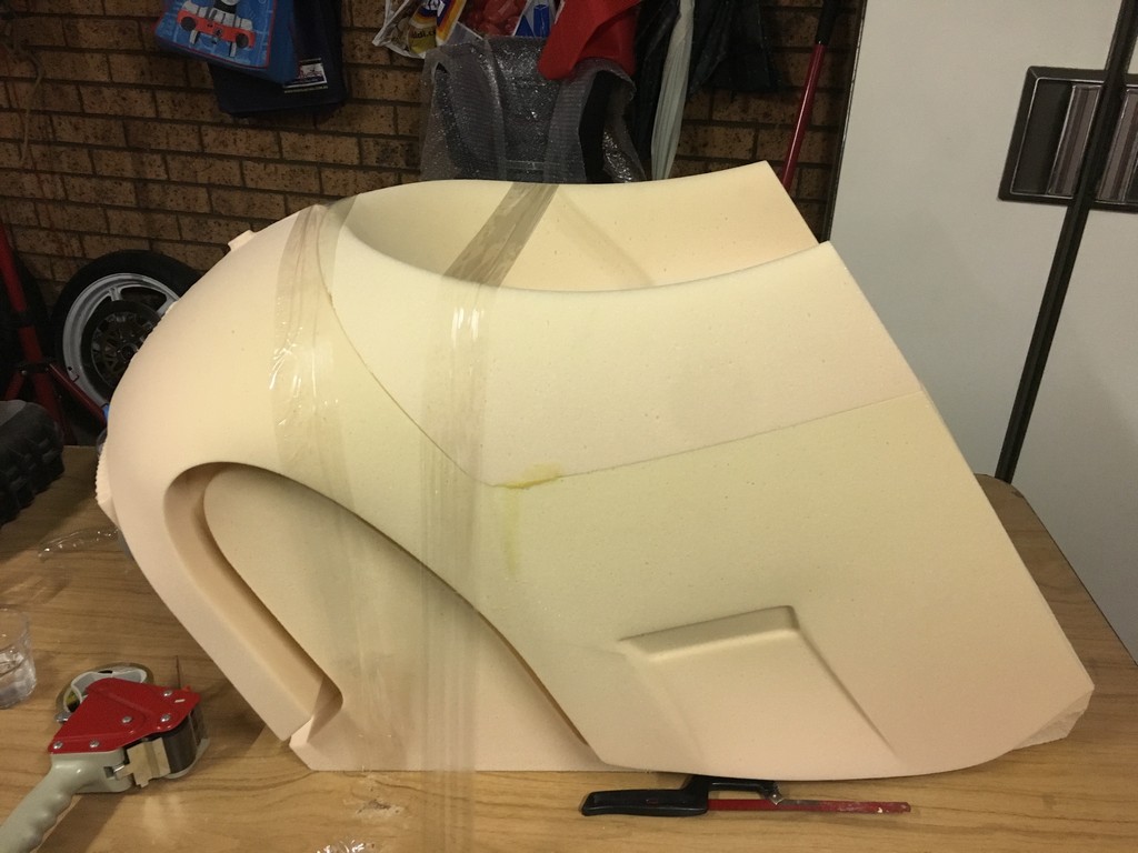
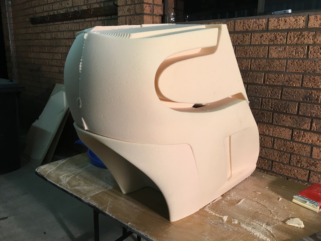


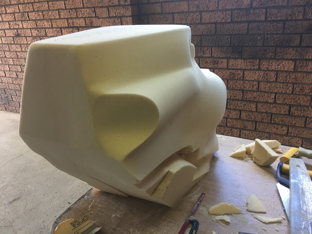
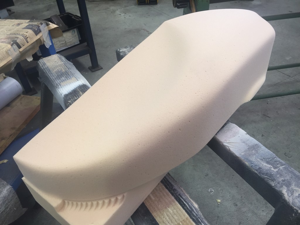
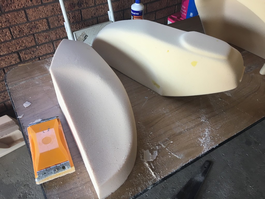
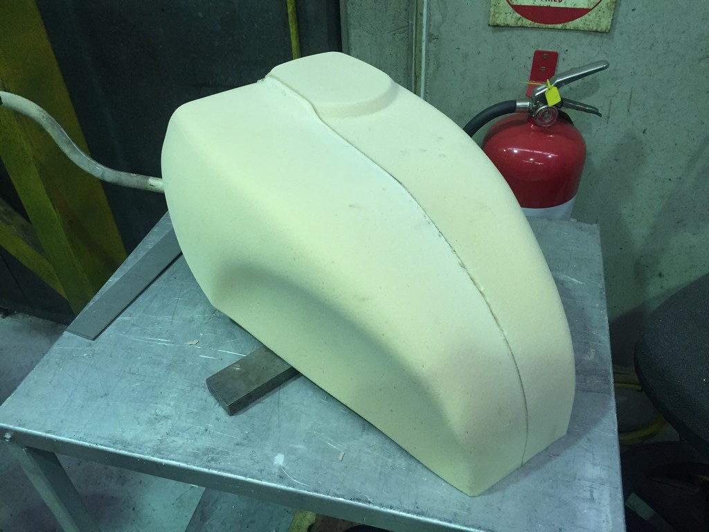
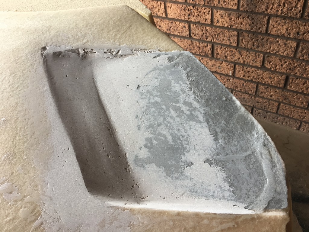
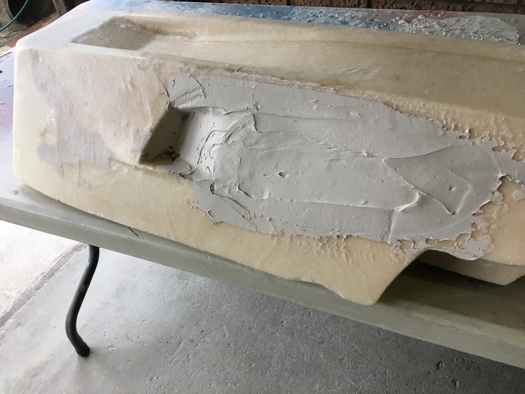
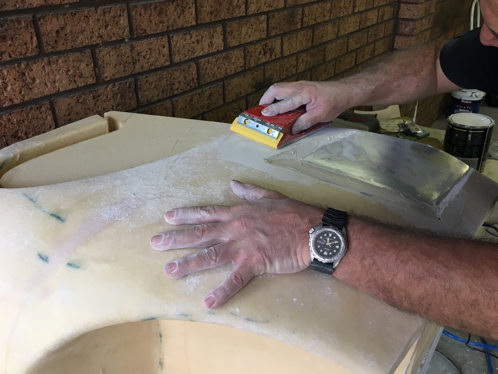
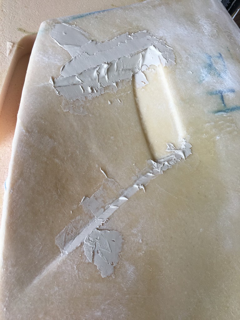
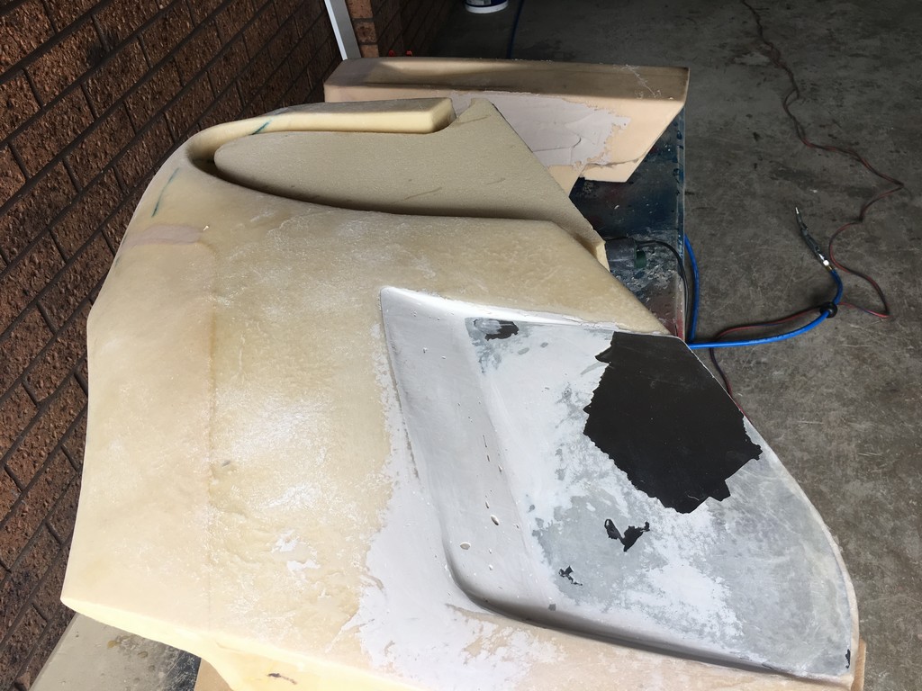
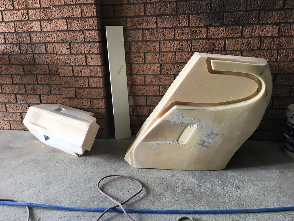
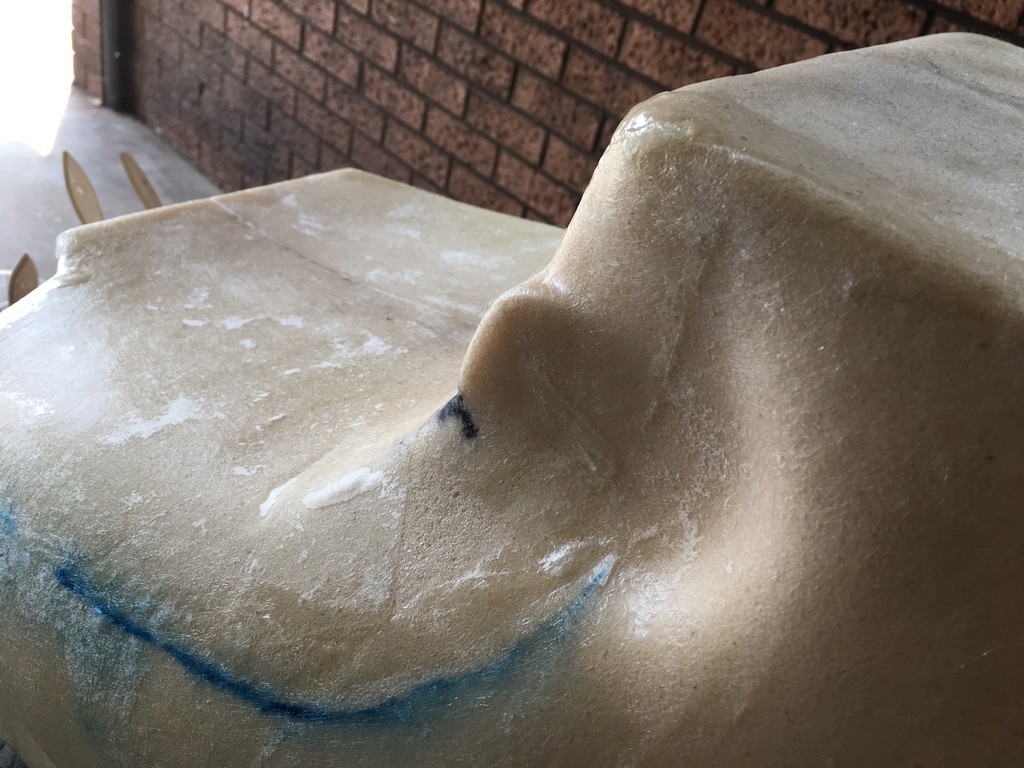
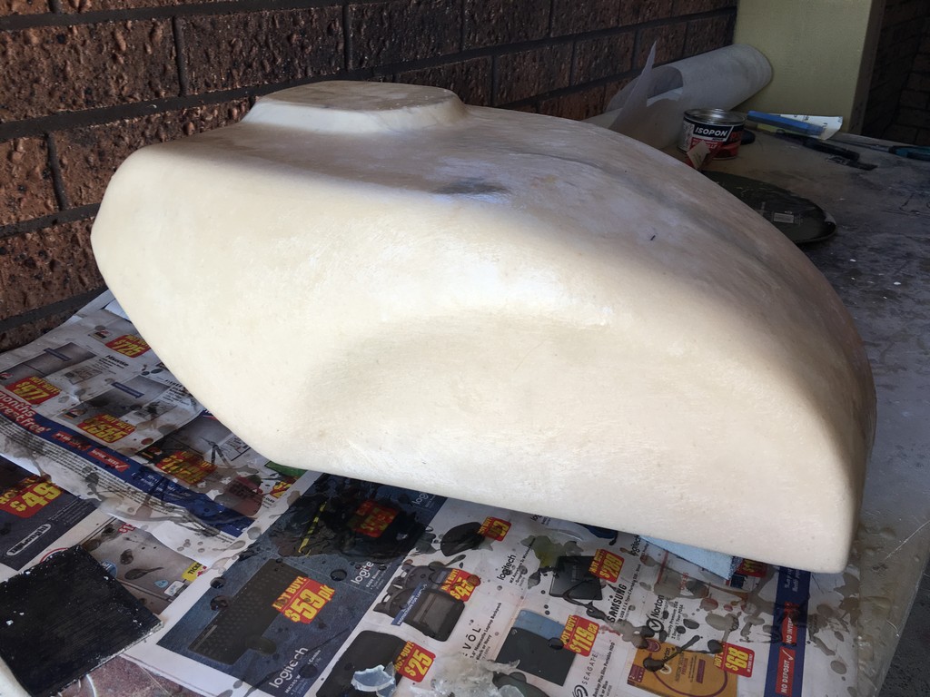
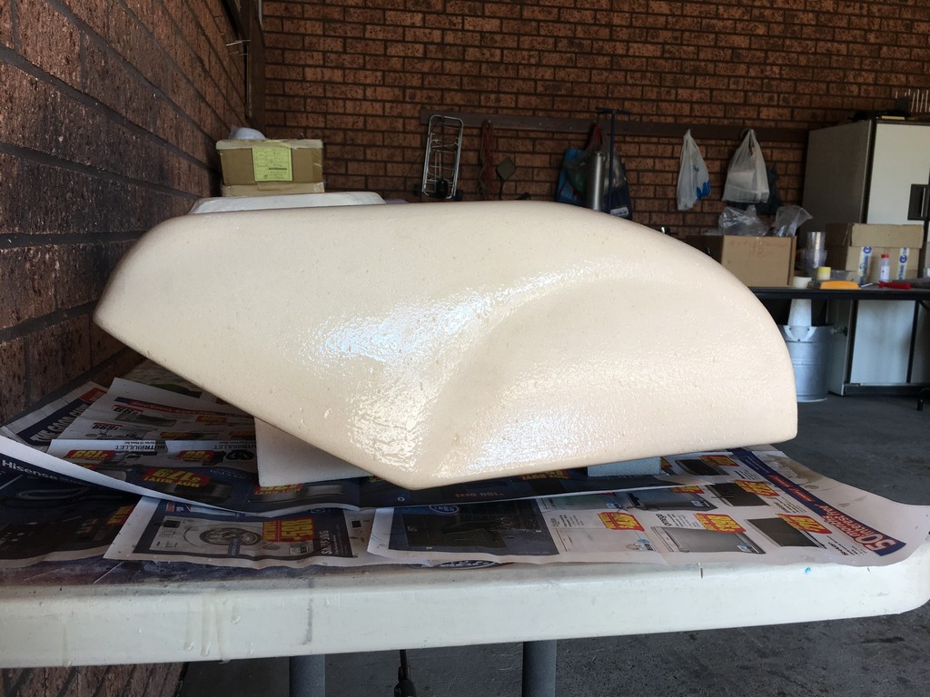
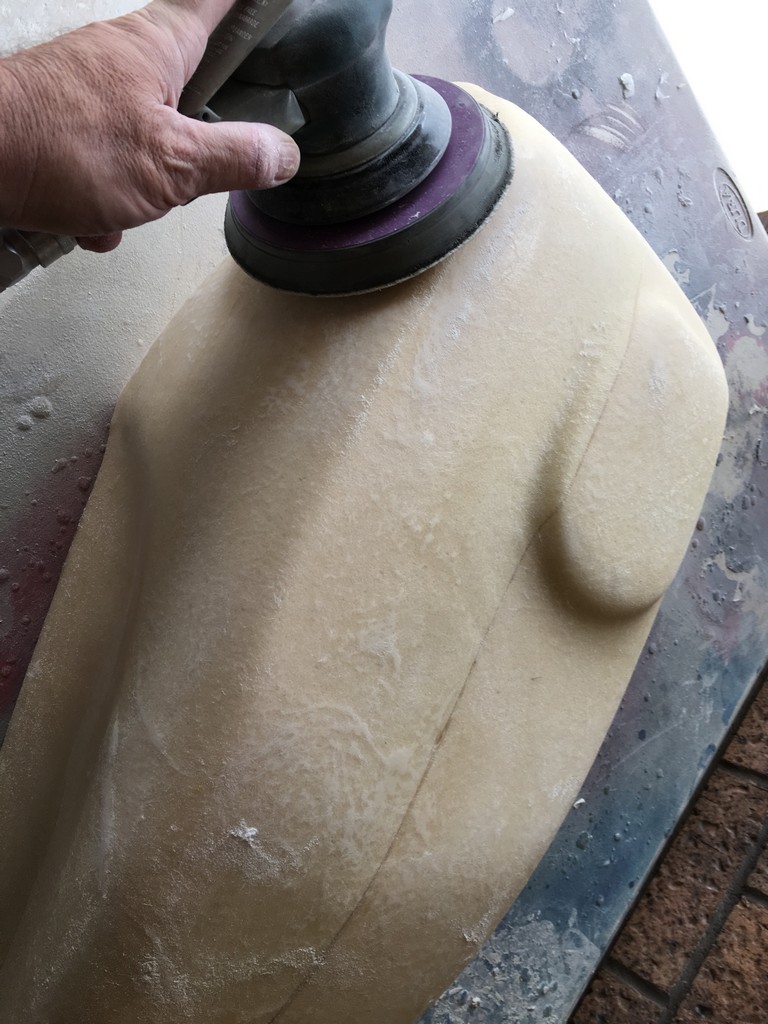
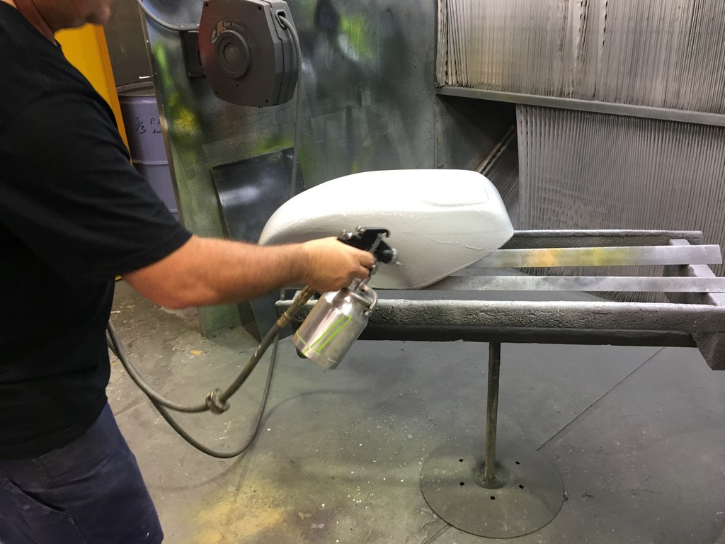
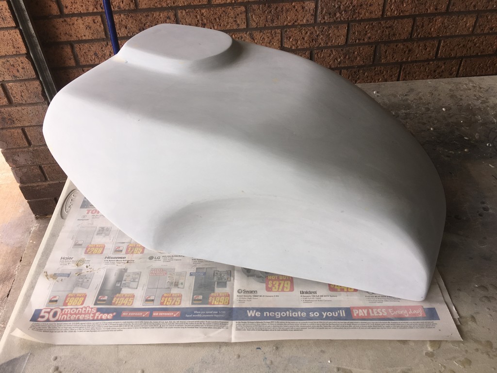
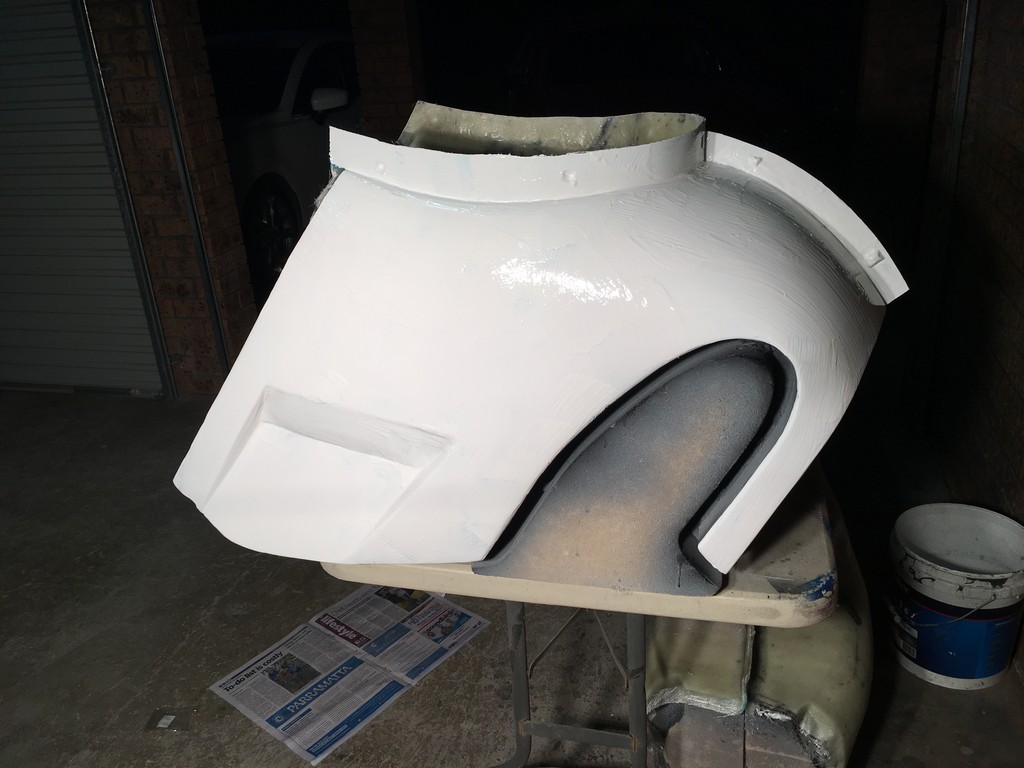
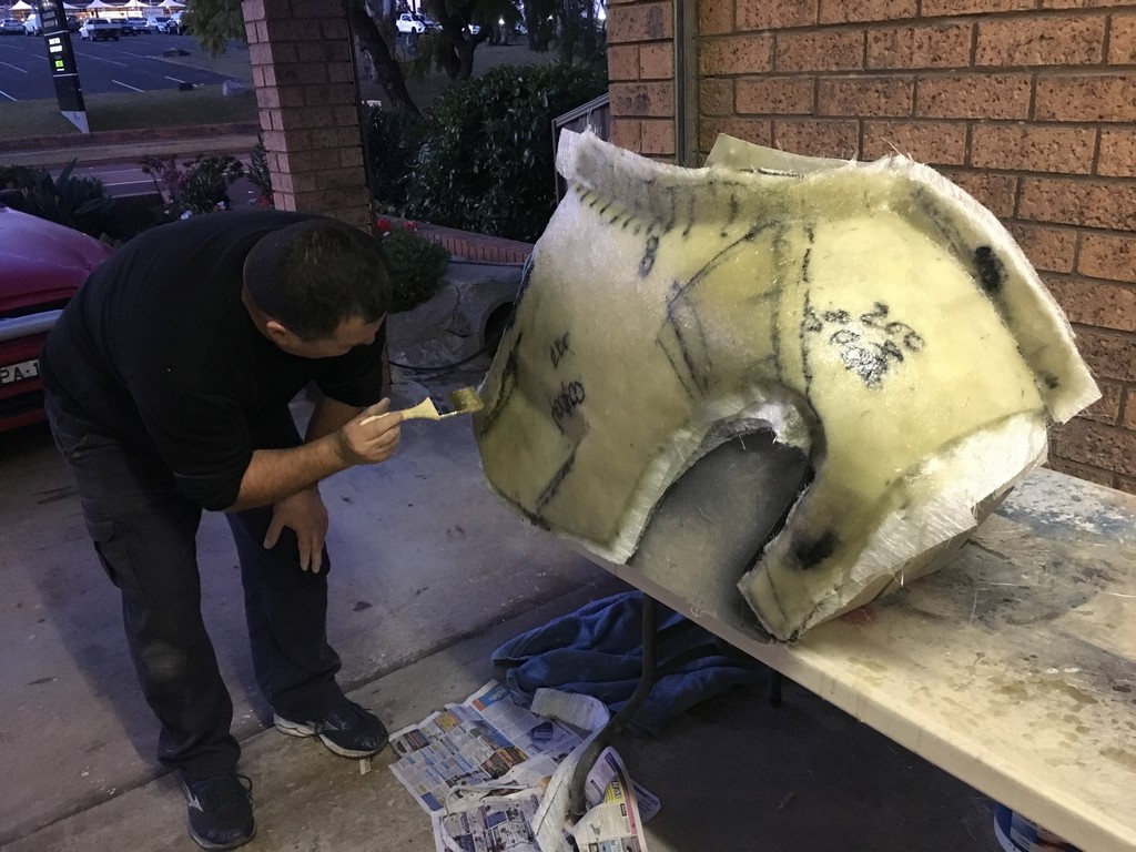
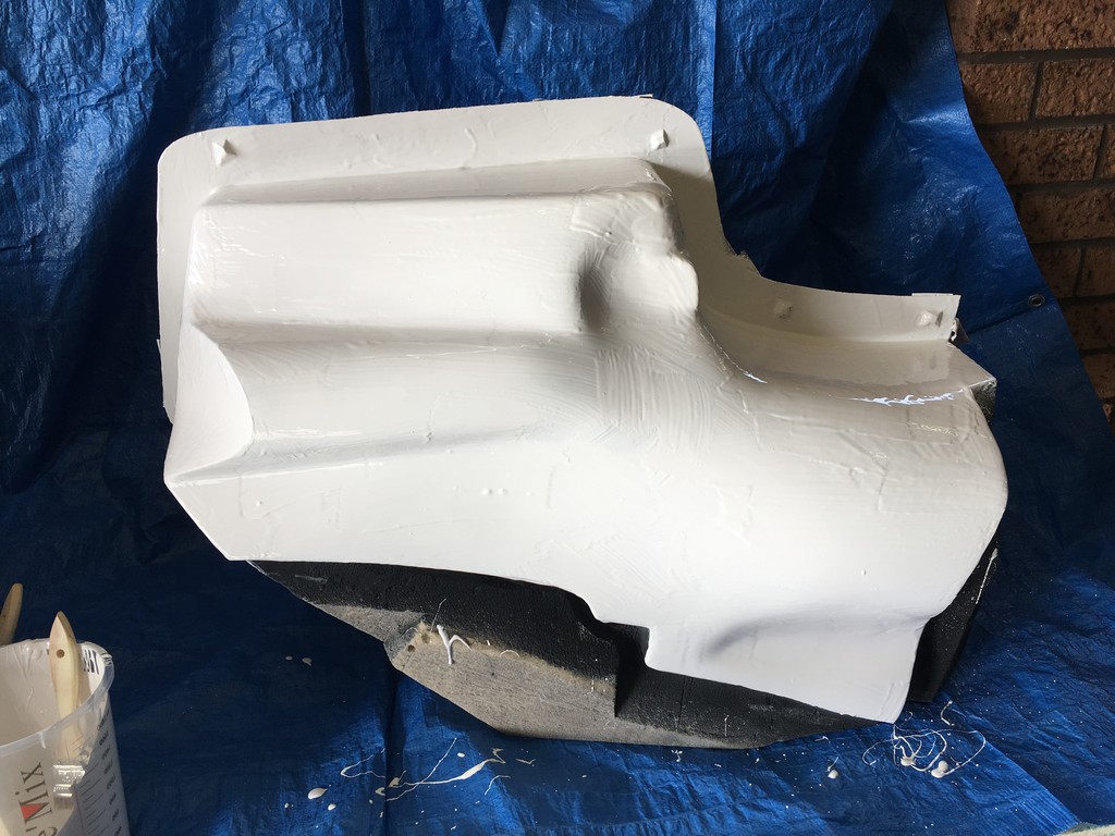
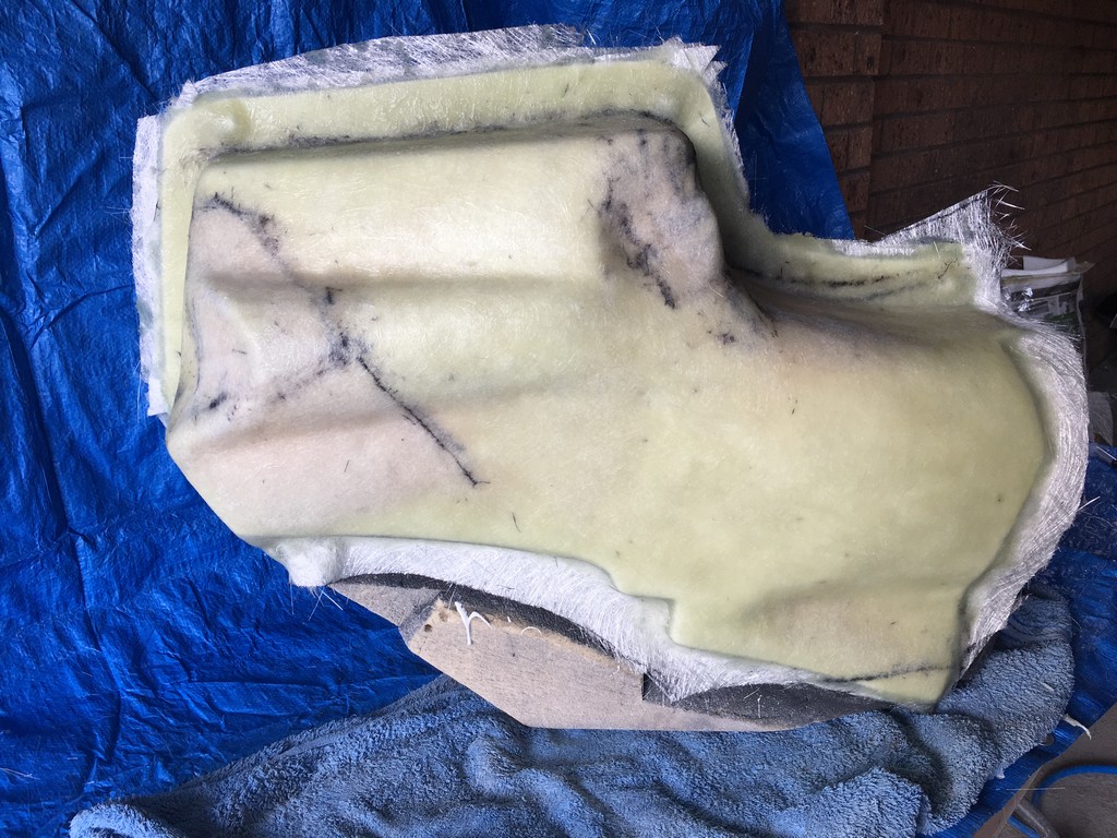
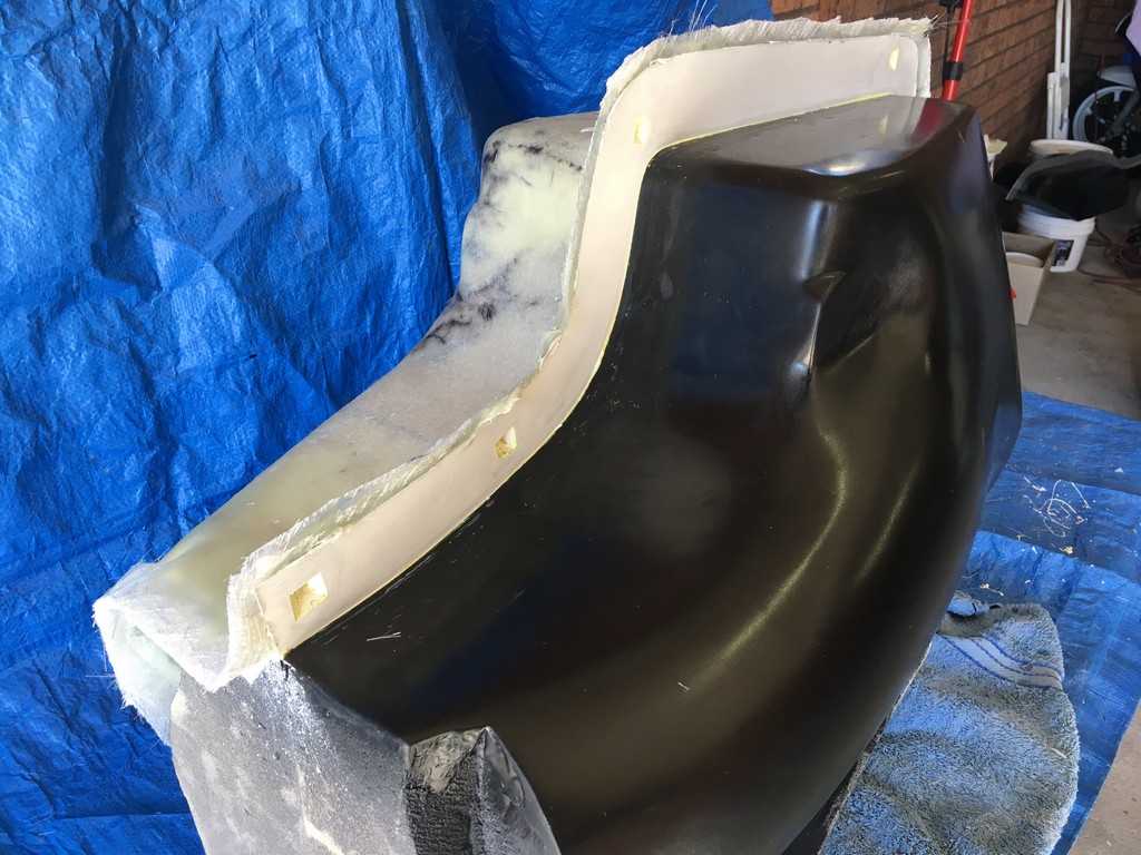
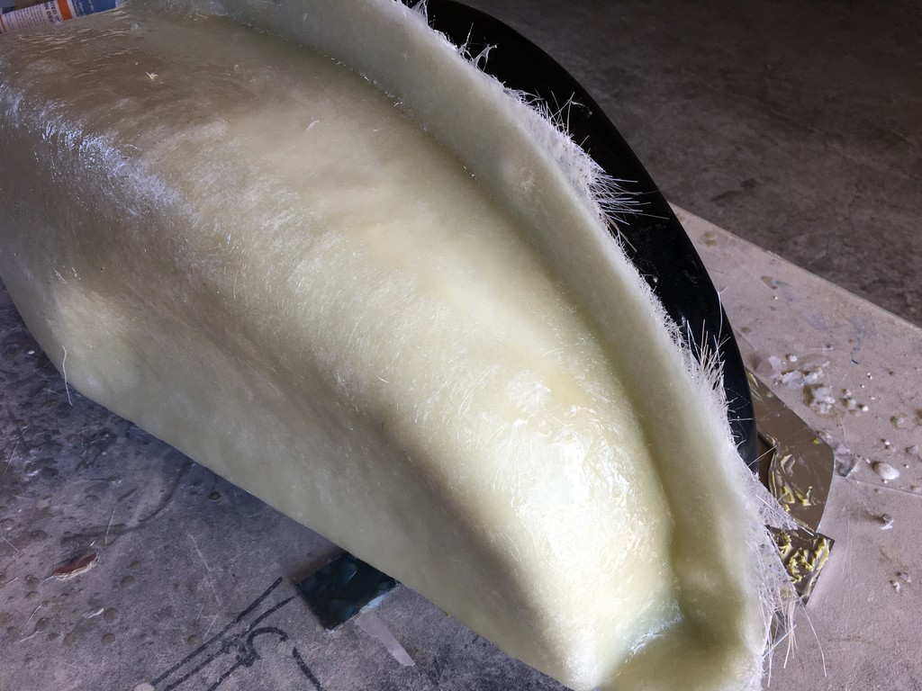
Finishing the foam plugs
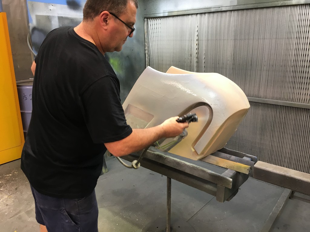
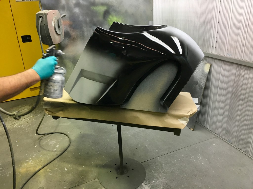
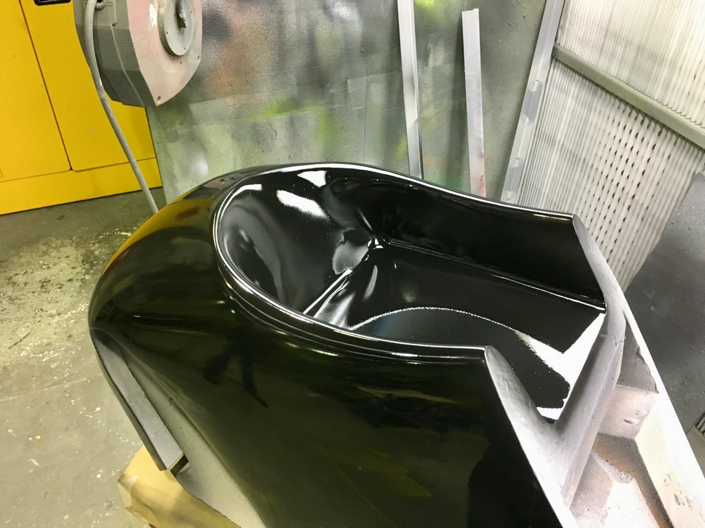
The quality of the surface finish of the final parts is highly dependant upon the quality of the plugs. To obtain a high quality finish the plugs were coated with a layer of fibreglass surface tissue and polyester resin. This provided a hard skin over the relatively soft foam which made the plugs easier to work with. At this point the fine details of the plugs were refined with lots of hand shaping, sanding, filling, priming and painting. I should emphasise lots and lots of shaping, sanding, filling, priming and painting. It was a very laborious, tedious and dusty part of the project but at the same time a critical part that had to be done right.

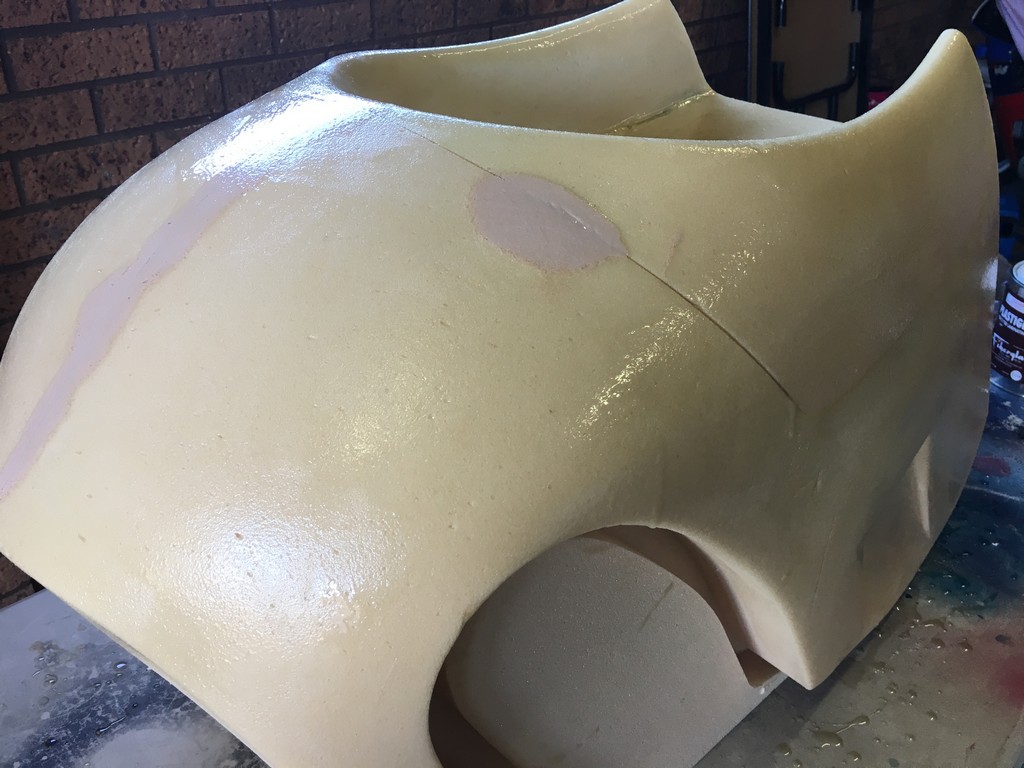
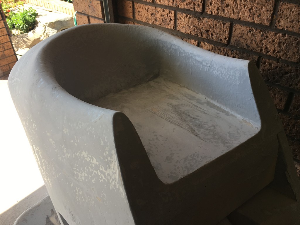


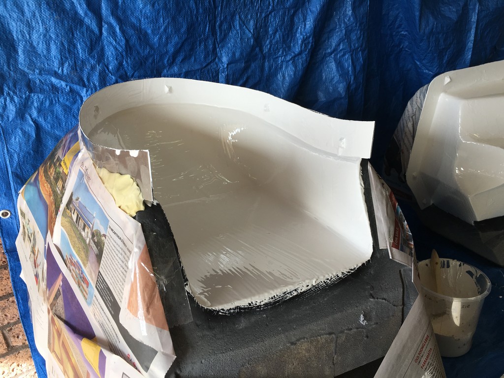
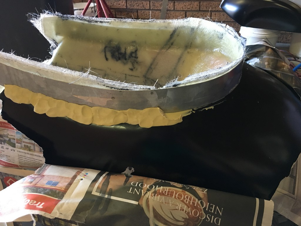
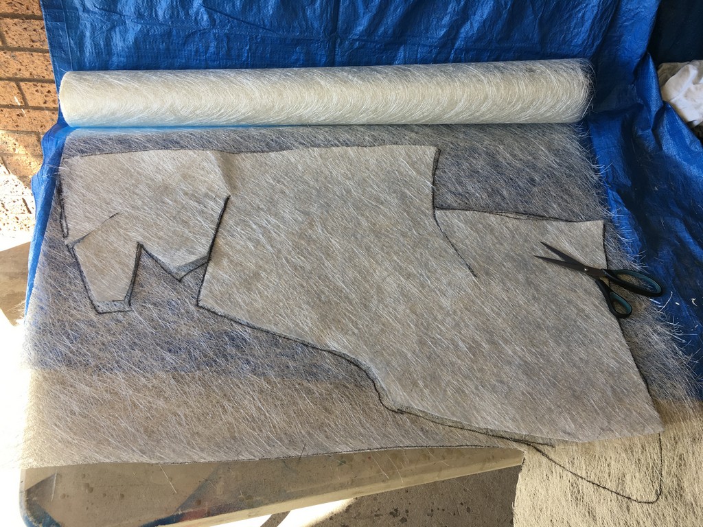
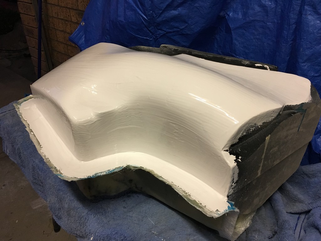
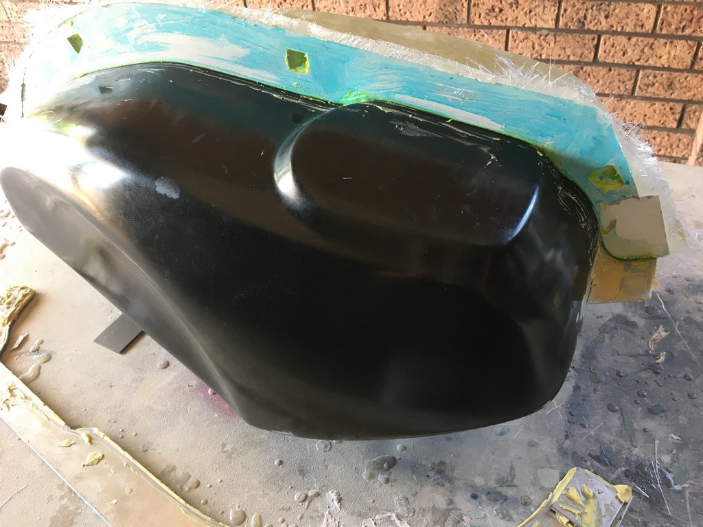
Making moulds from the plugs
Making moulds of the finished plugs was carried out using standard fibrglassing techniques.


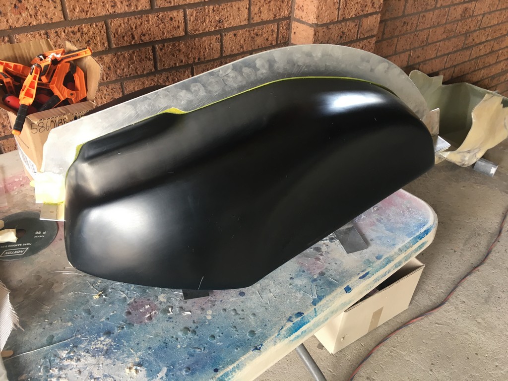

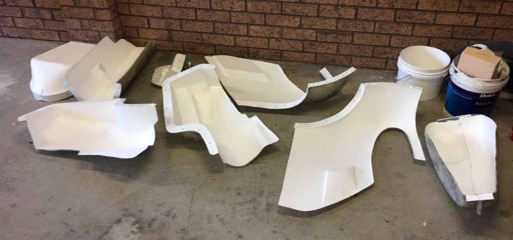

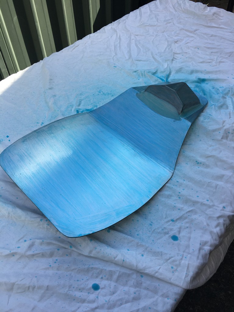
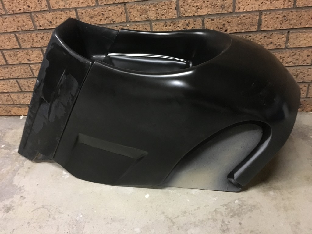
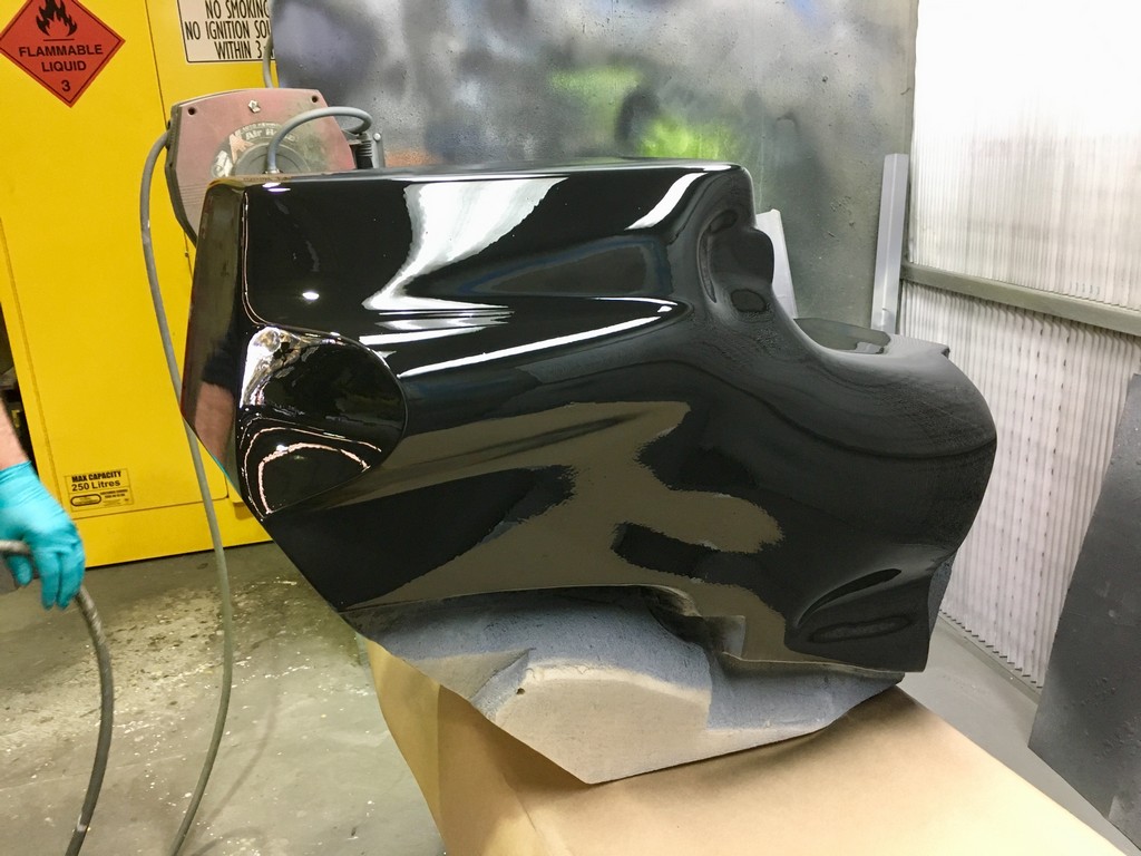
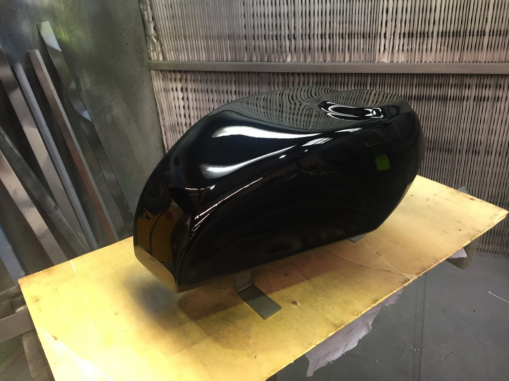
Completed parts
All the above work was done in house and by the time the plugs and moulds were completed we were thoroughly fibreglass fatigued! So therefore, we treated ourselves to a break from the fibres and fumes and outsourced the manufacturing of the laminates to a specialist fibreglass company in Sydney. When we got the parts back all that was left to do on the main fairing was to create a lap joint to fit the upper cowl to the bellypan.

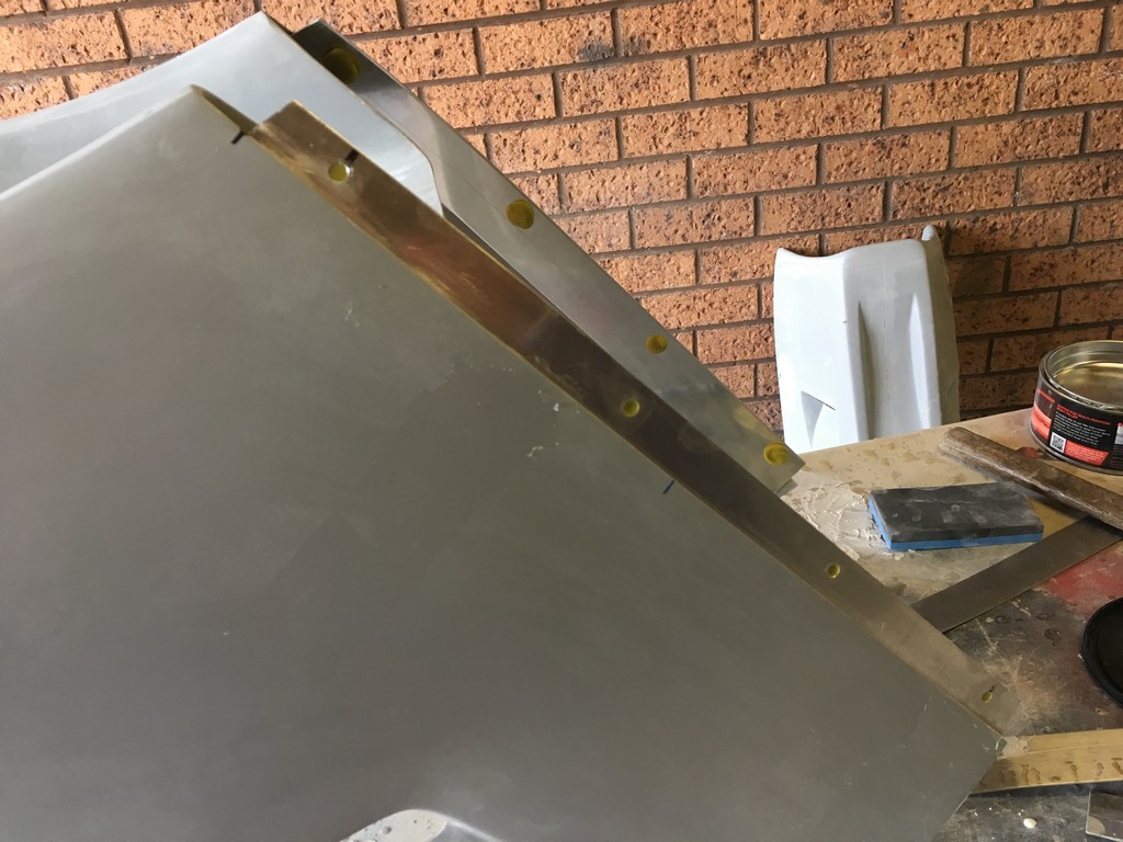


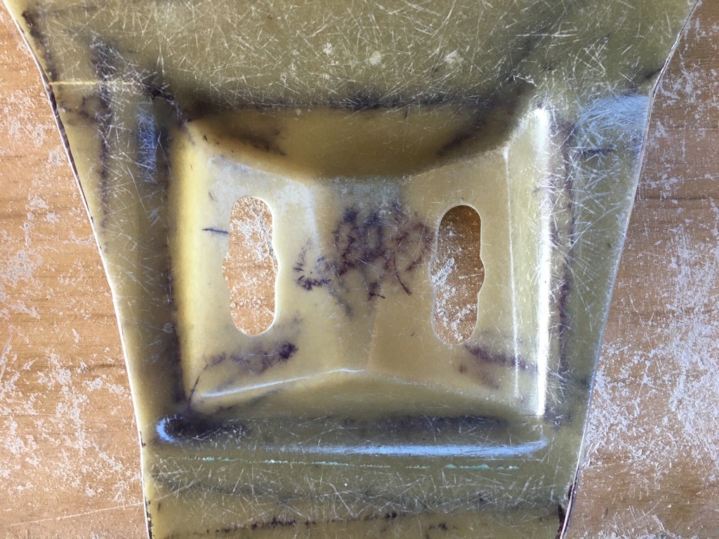
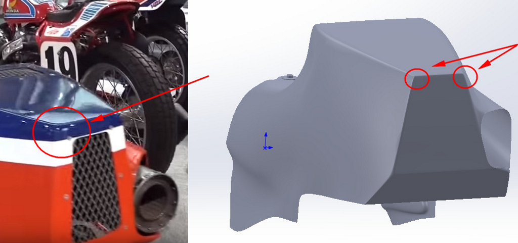
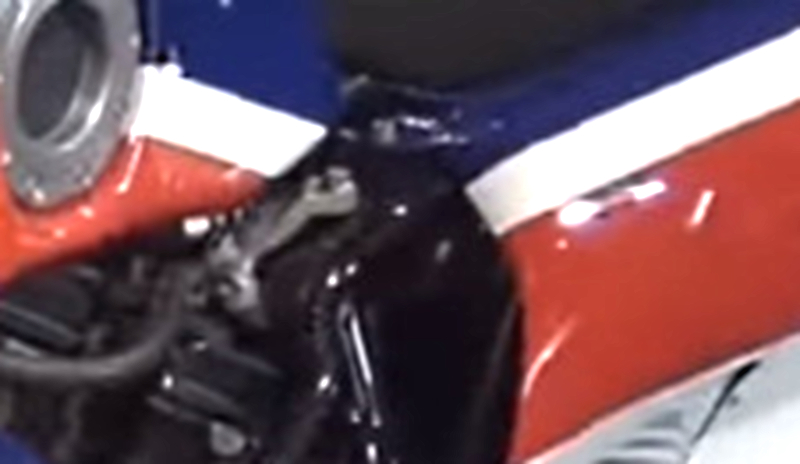
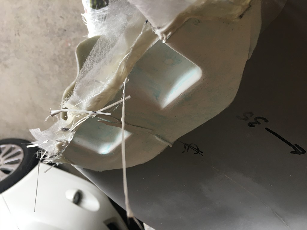
We’re quite happy with the way the bodywork parts turned out considering we had nothing to work with except for some images on the internet. Despite pouring over the images with a fine tooth comb a particular detail popped up that we hadn’t noticed before. In this case we noticed that the forward seat mount isn’t flat like we had made it but in fact had two recesses for the mounting bolt holes. After spending so much time on the bodywork development process we could’ve easily dismissed this oversight and left the seat as it was.
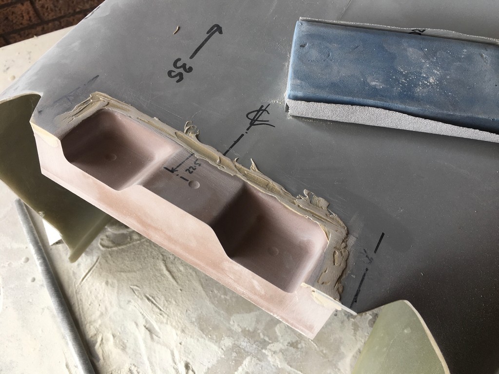
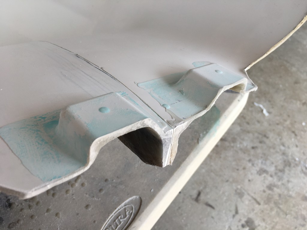
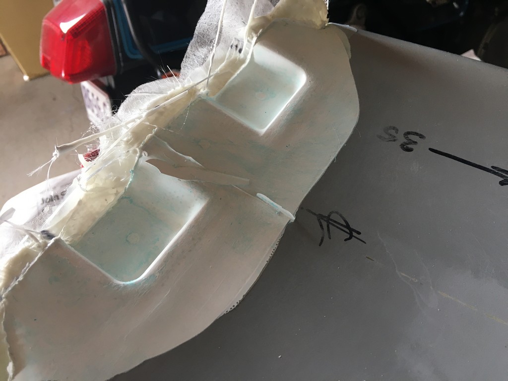
However, we have come so far and made such an effort to maintain fidelity with the original appearance we just couldn’t let it go. The dimensions of the mount detail was worked out and a piece of tooling board machined to replicate it. We then cut out the section of the newly made fibreglass seat and bonded the tooling board into position. The seat was remounted in it’s mould and the mould modified to include the mount detail. From there it was a simple case of re-glassing that section of the seat to include the mount recesses.

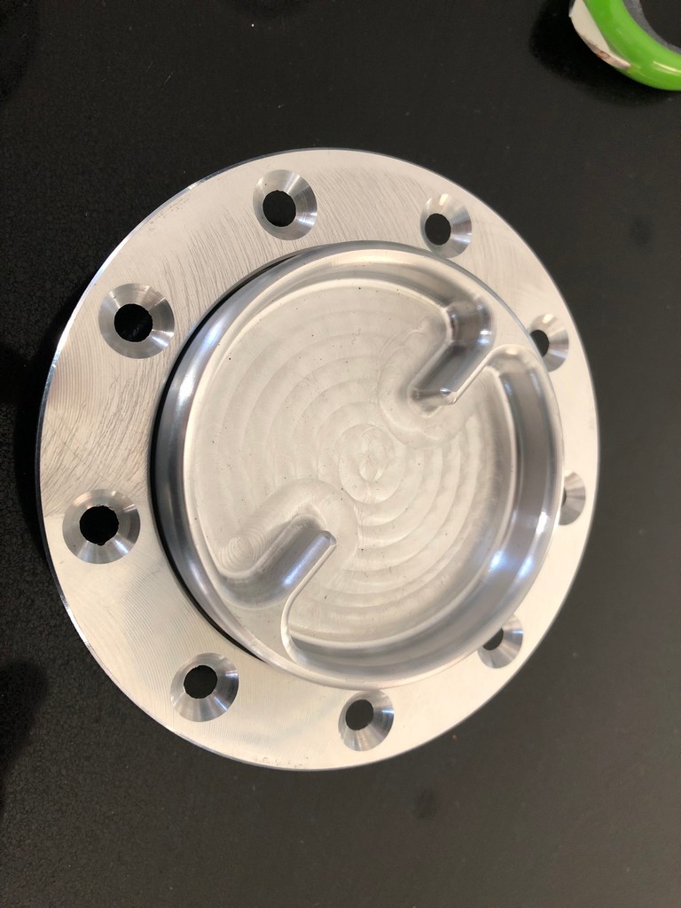
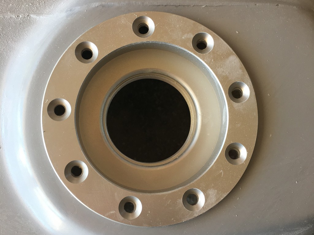
Turning to the underside of the tank a floor was constructed with twin fuel outlets as featured on the original FWS1000. A cap, baffle and vent was was also incorporated.