Chassis Design & Construction
The frame of the FWS1000 was typical of the TT-F1 era. It is a wide perimeter twin loop ‘diamond’ style made from steel tube. Constructing a replica from the available photos seems a straightforward enough process until you begin to delve into the intricacies of motorcycle chassis design.
There are many aspects to consider in the design including basic dimensions like rake, trail, weight bias and wheelbase. Fortunately, the Japanese RACERS magazine vol. 10 featured the Honda V4 line of racing bikes and included a specification table with a number of handy dimensions.


The FWS1000 raced with a 16” front and 18” rear wheel combination. Our replica will use 17” wheels front and rear so we have to consider how that will affect the geometry of the chassis and suspension as well some practical issues like front tyre to engine clearance etc. One critical piece of information is knowing where the centre of gravity is located. When you don’t have a physical object to measure the best you can do is estimate where it is. It’s important to know because it has a direct bearing on rear suspension squat behaviour and where to locate the swingarm pivot in relation to the engine’s output shaft.
So along with some help from Tony Foale and John Bradley and a healthy dose of the ol’ suck it and see approach, it was time to start drawing.


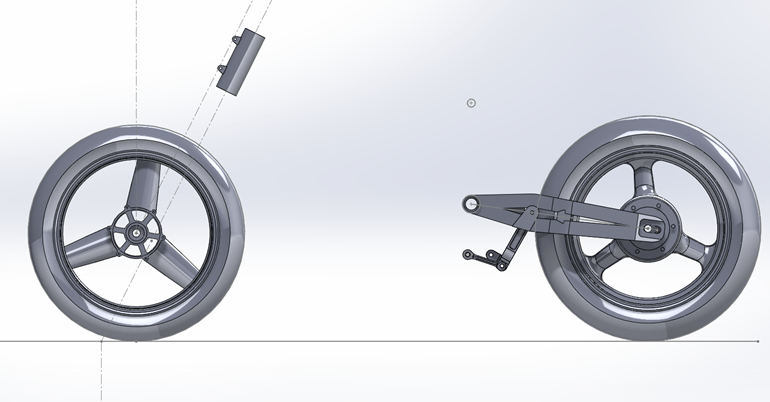
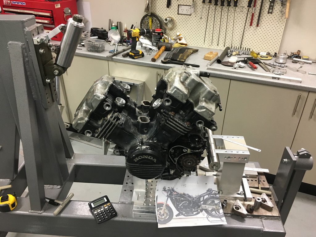
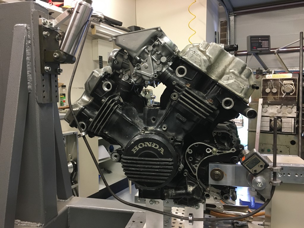
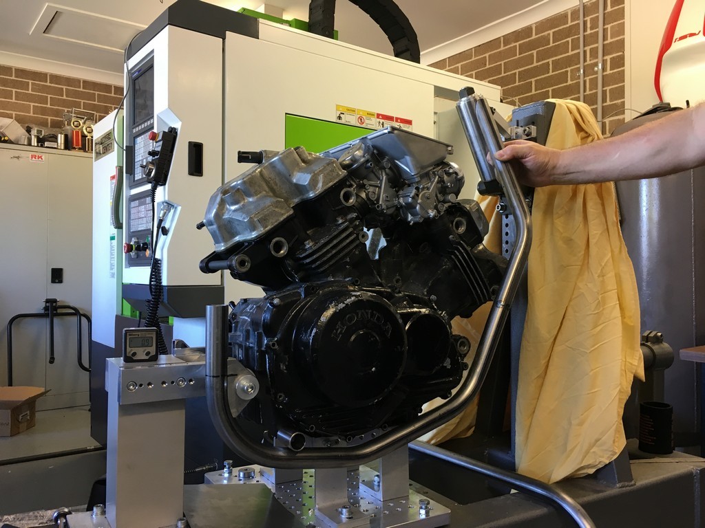
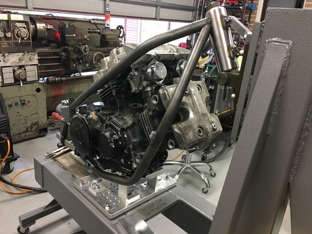
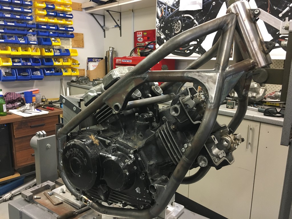
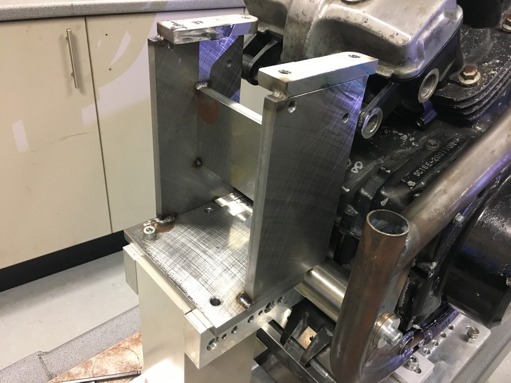
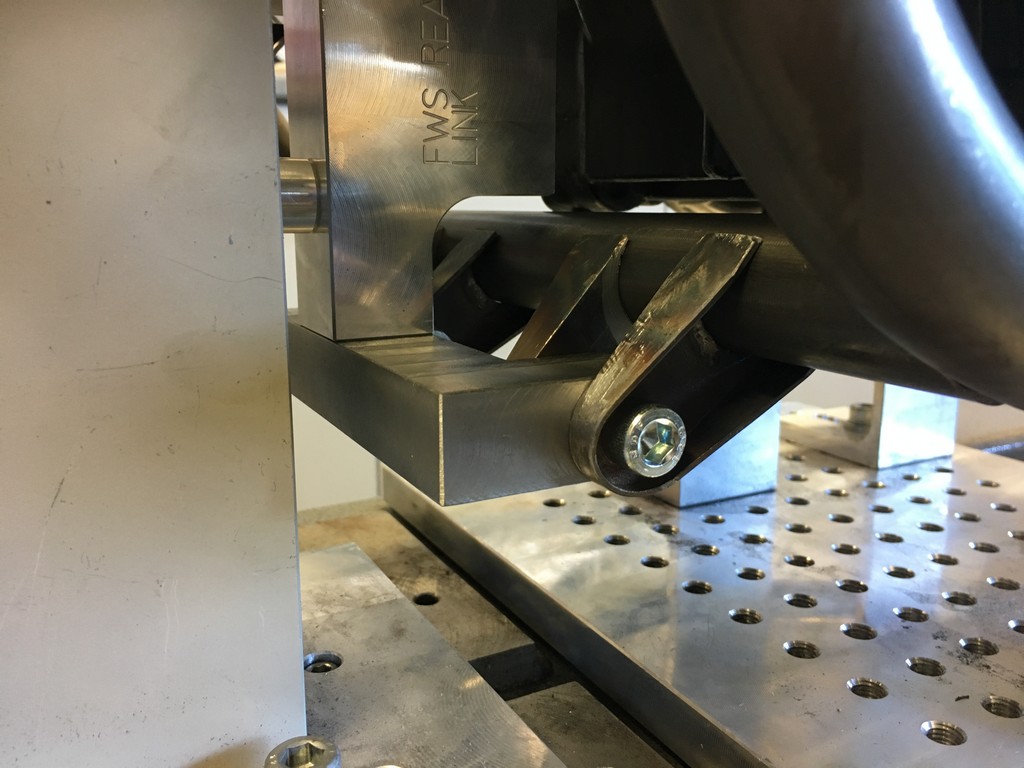
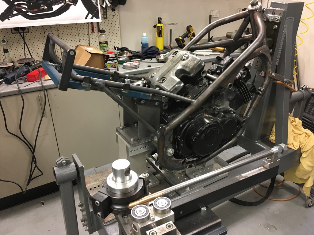
Now that we’ve established the basic chassis parameters it was time to start building. We began with making and setting up the steering head tube, swingarm pivot and suspension link parts.

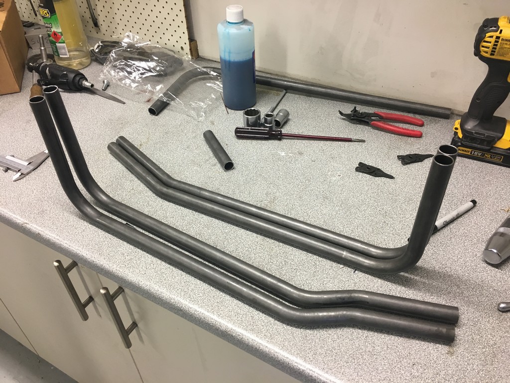
With those components in place we could start with fitting up the tubes. Let the bending, cutting, grinding and welding begin!


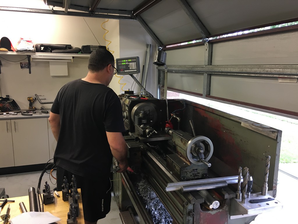


A special shout out to Darrin Treloar for helping us with his tube bending prowess. It’s always good to have a world champion in your corner.


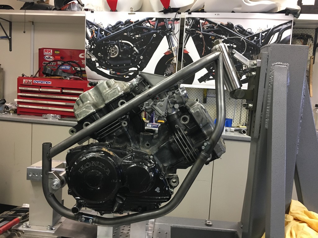


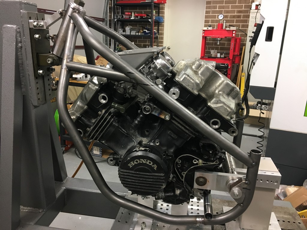
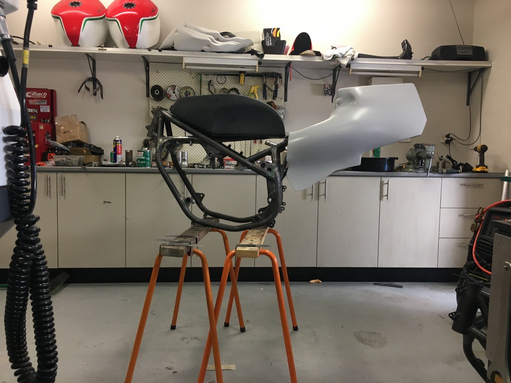
With the main frame completed it was time to turn our attention to the subframe. The tubes of the subframe wrap tightly around the rear cylinder head particularly on the left hand side and form the upper mount for the rear shock and seat unit. Bending the tubes and arranging the fixturing was quite a tricky set up.
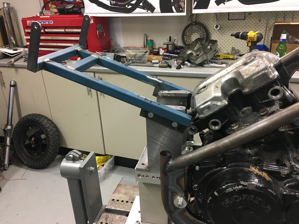
With the fixturing in place the subframe structure was welded in place.
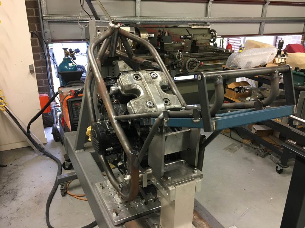

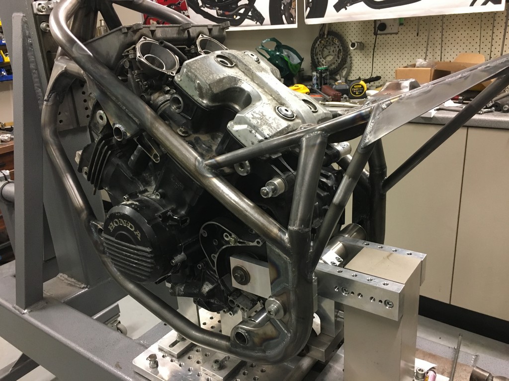


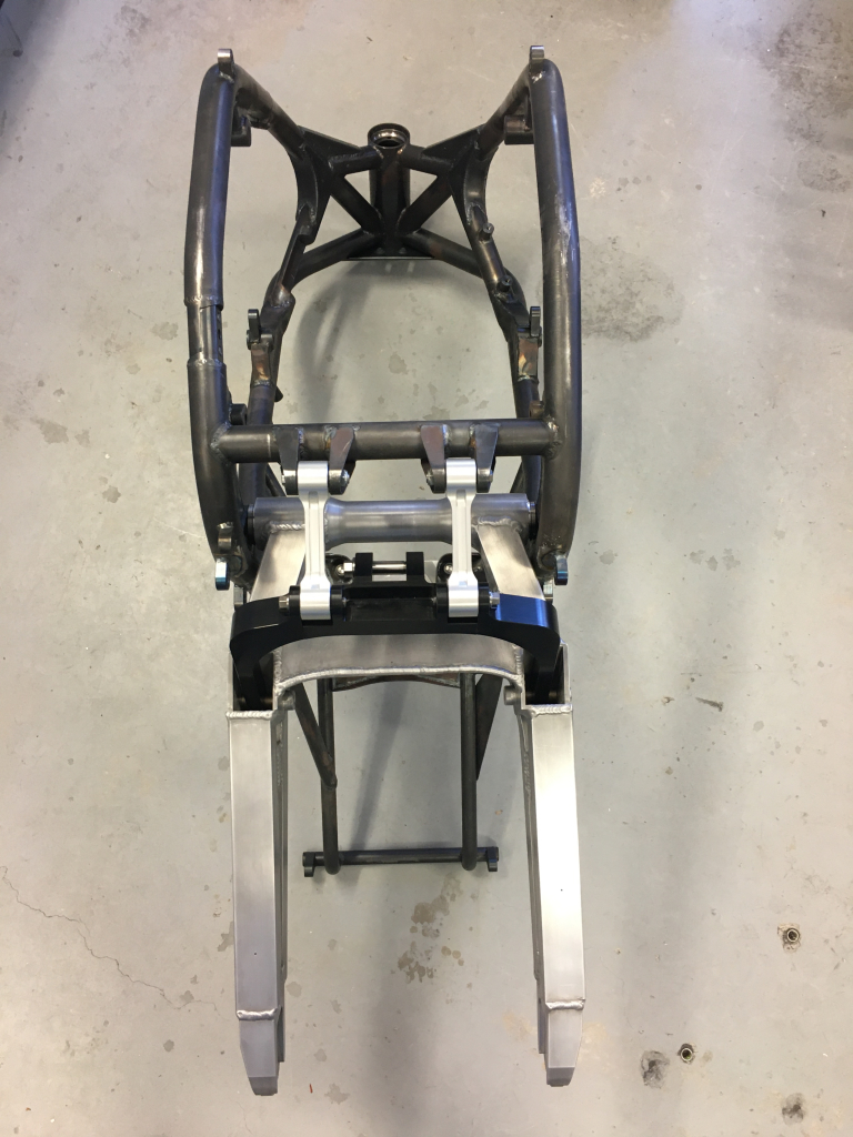
The frame is released from the fixture and we can start to see a motorcycle emerging!
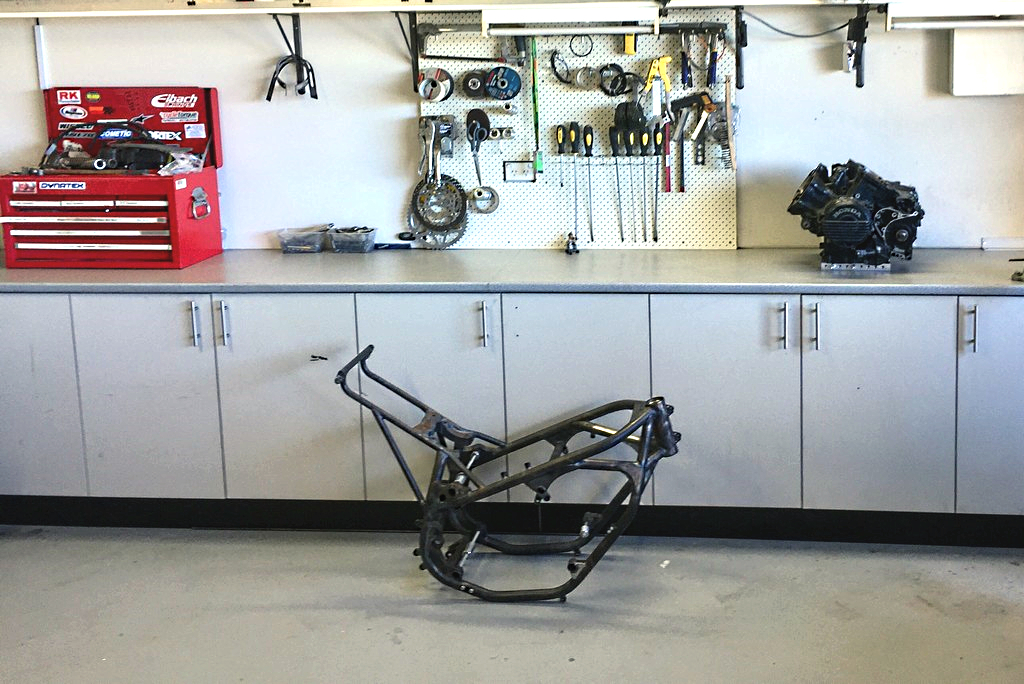

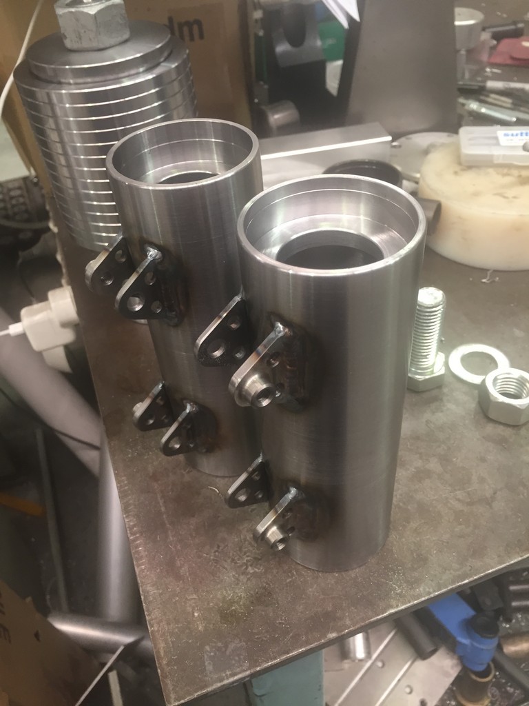
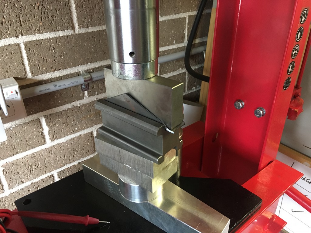
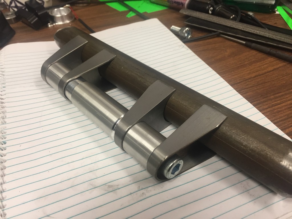
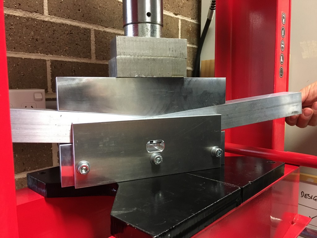
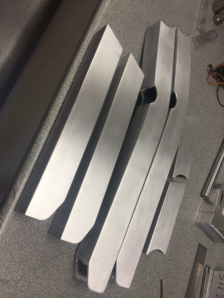
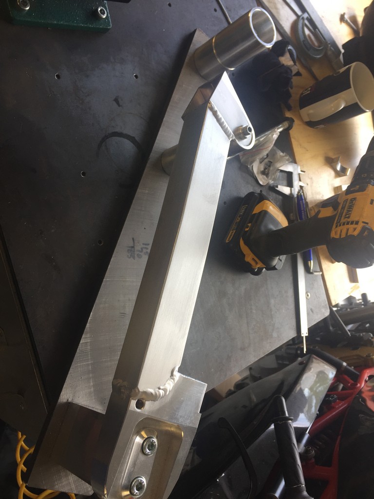
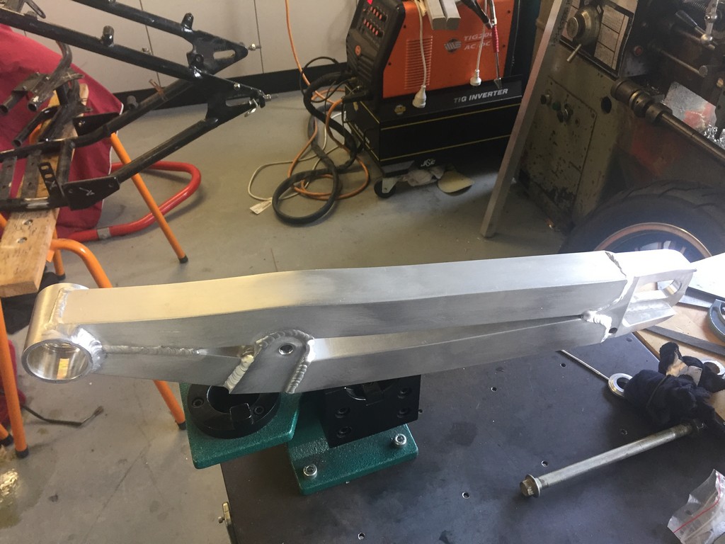
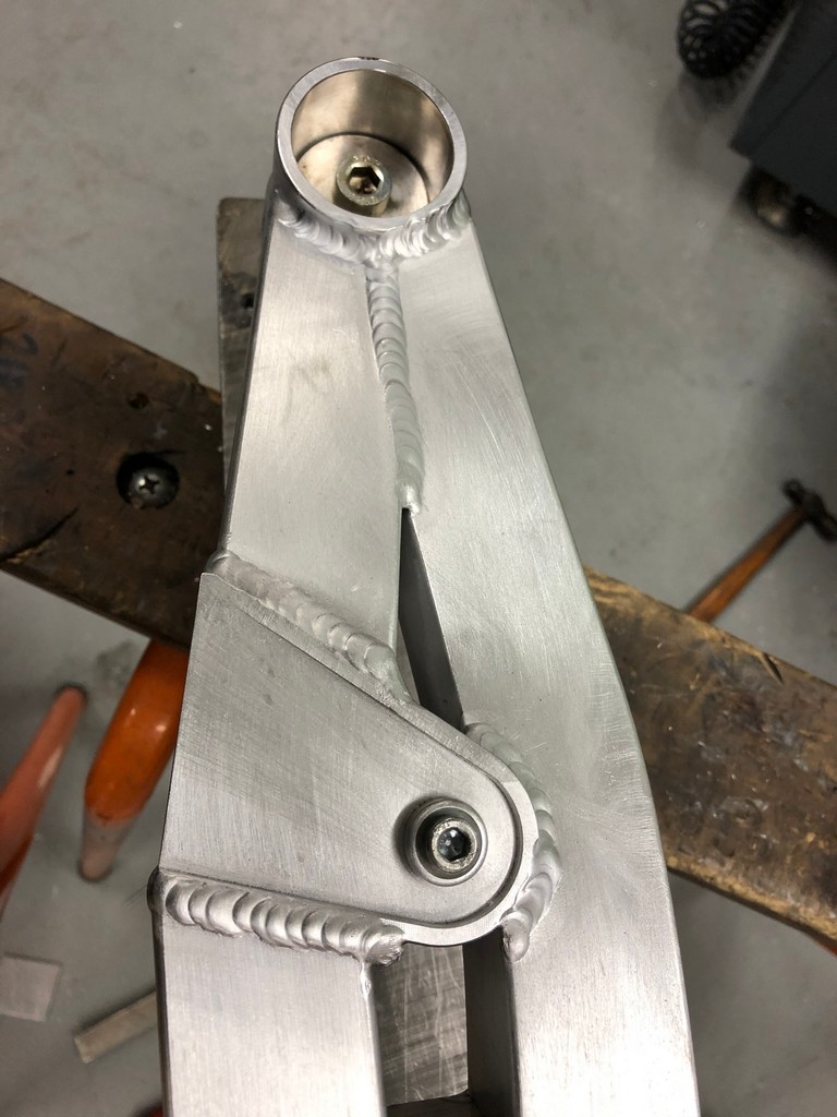
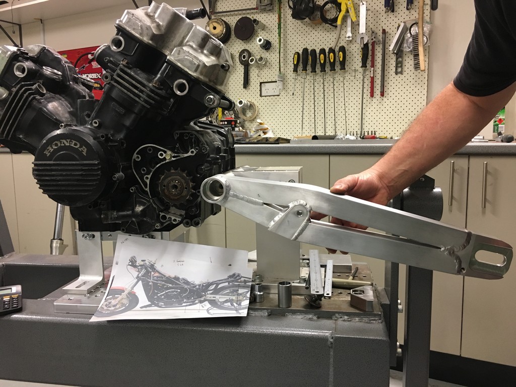
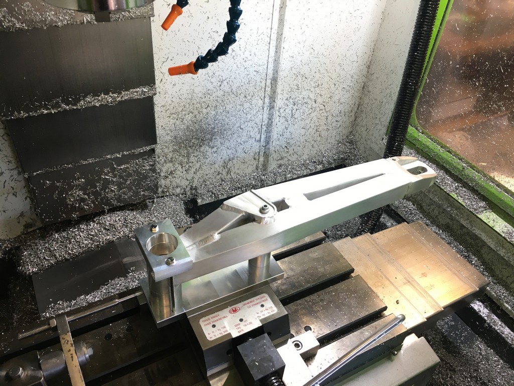
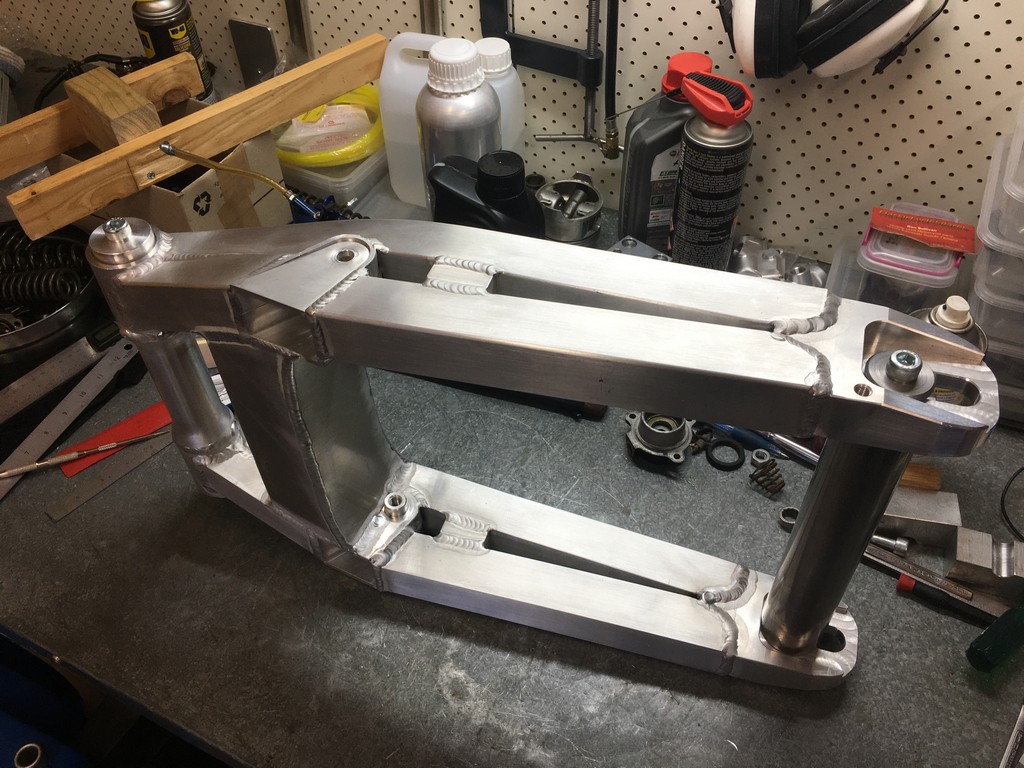
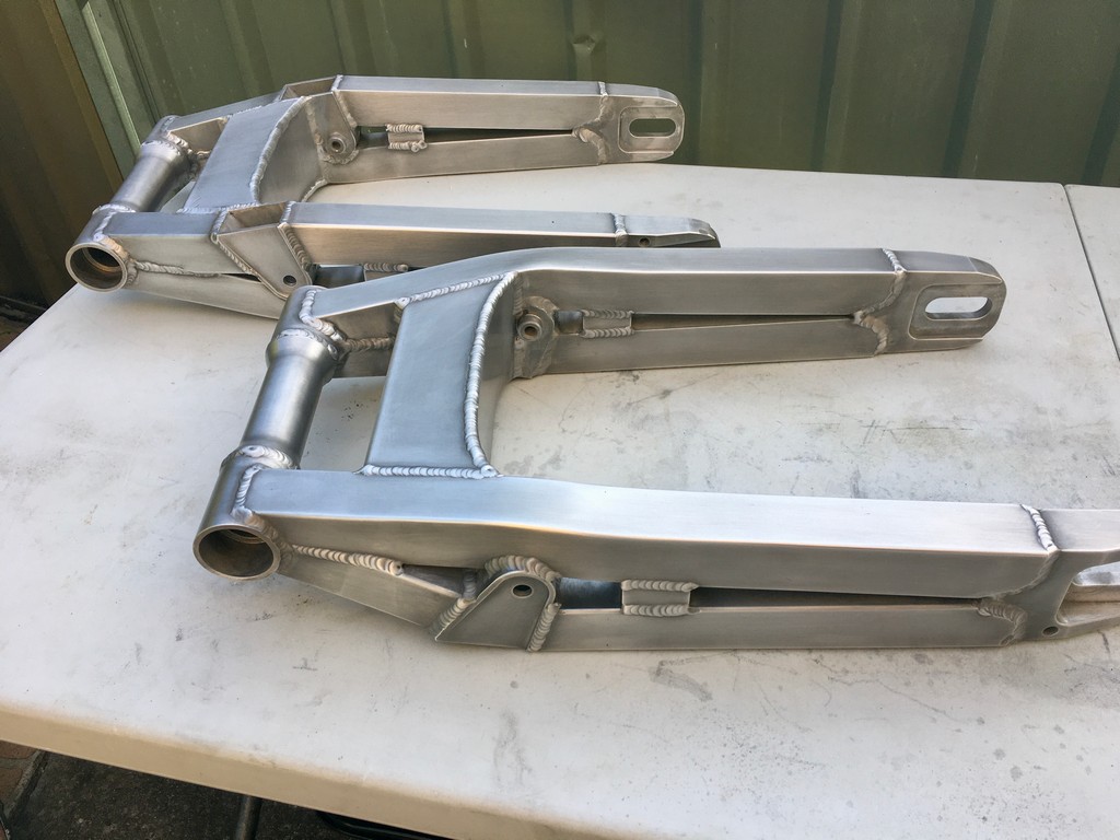
The swingarm of the FWS1000 is a unique and complex multi-piece aluminium weldment design which was quite the challenge to fabricate.


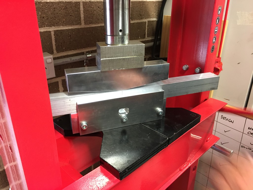
The upper section of each arm is a single piece of extruded aluminium box section with a compound curve bending inboard and downwards towards the pivot.The bottom arm member incorporporates the receptacle to accommodate the suspension links. The images below show the steps involved in the fabrication process.


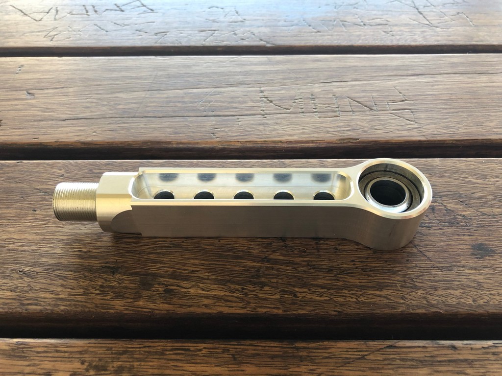
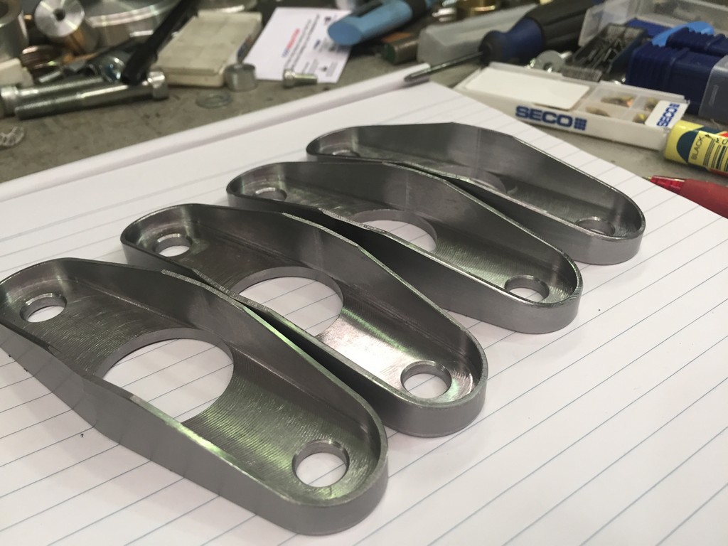
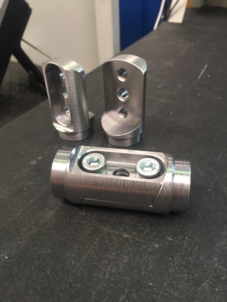
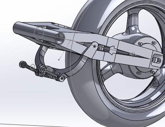
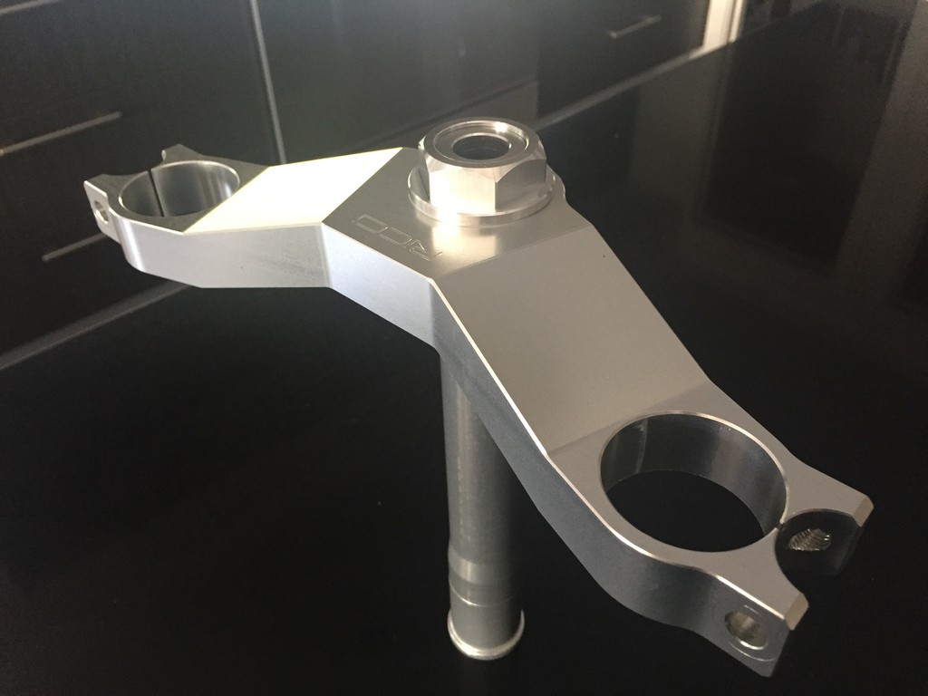
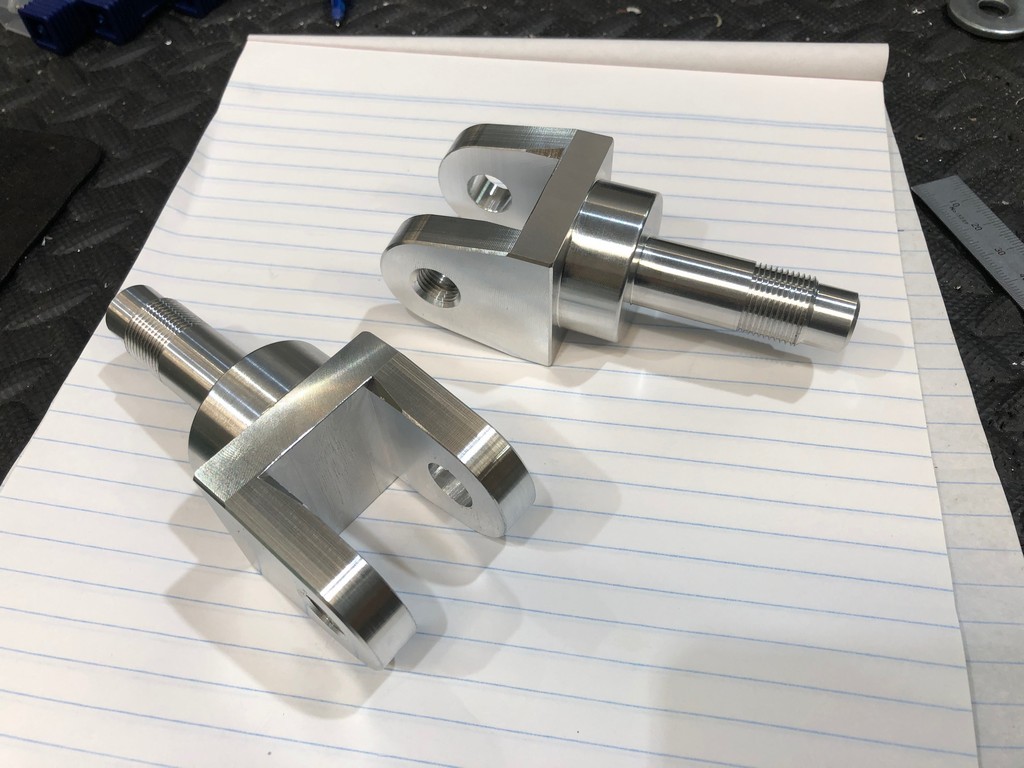
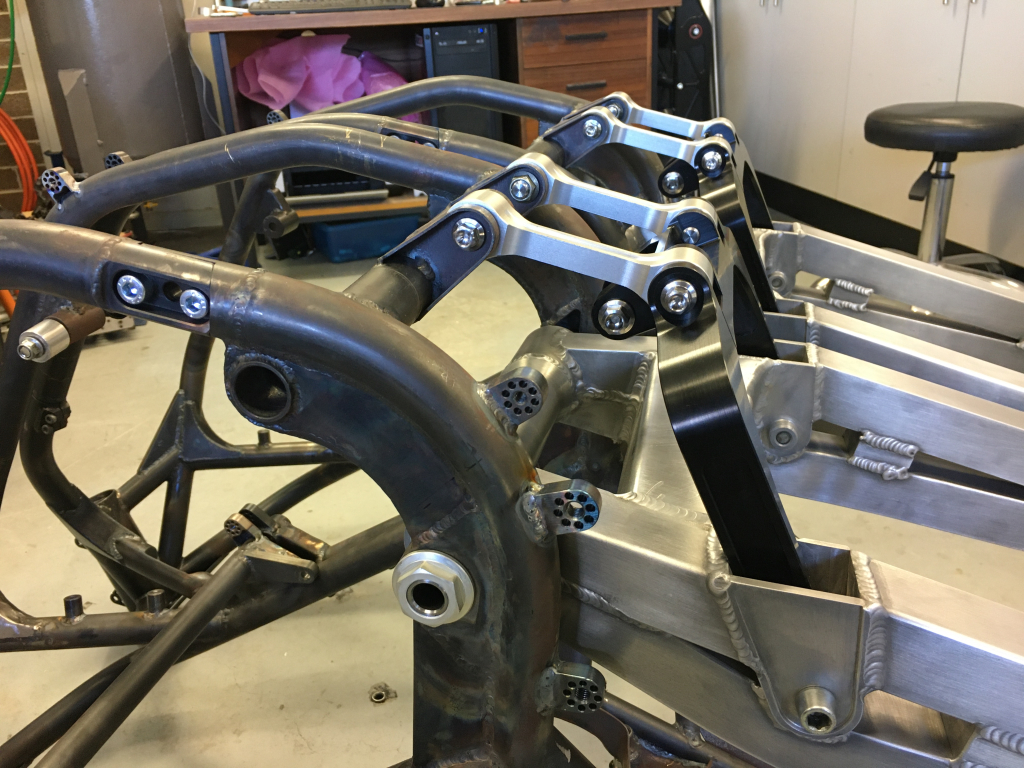
Working through the long list of parts needed to push this project along. below are some images of the triple clamps and rear suspension linkage parts. All parts designed and machined by Mario of RICCI Engineering http://riccieng.com/. If you need any bespoke bike parts made hit him up through the website of the facebook page https://www.facebook.com/RICCIEngineering/


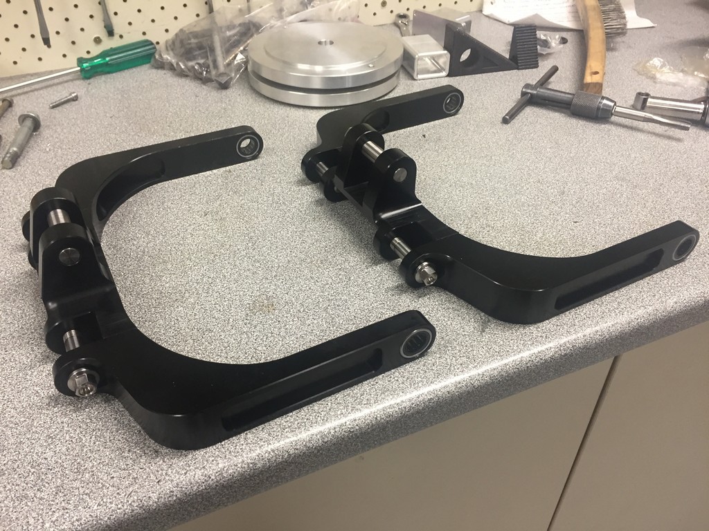
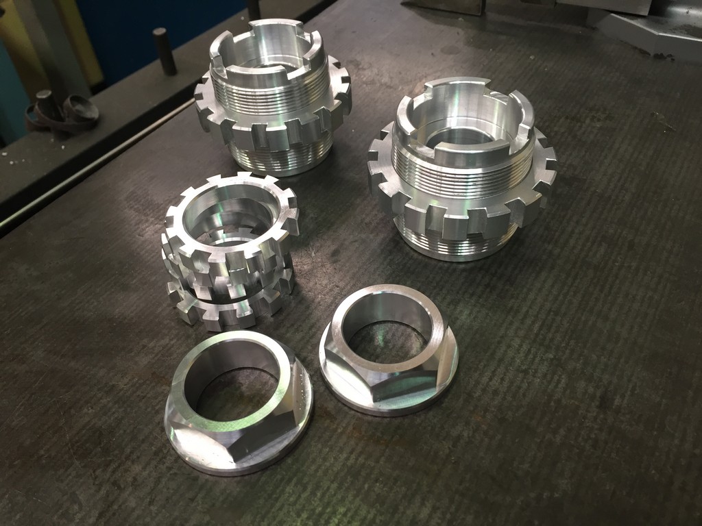


Honda employed an odd layout for the rear suspension linkage arrangement on the FWS1000. Then again it was the early days of single shock linkage style suspension so they had to start somewhere. It’s a finicky arrangement that was difficult to replicate and manufacture. A good reason to not persist with it!

Trying to maintain the authenticity of appearance with the original FWS1000 is a key pillar of this project and which drove our decision to use Honda’s venerable Comstar wheels. Being destined for the racetracks of the 21st century the original wheel diameters of 16″ front and 18″ rear were not going to be suitable. Therefore 17″ front and rear they must be in order to avail ouselves of the latest rubber.
Wheel diameters had to be matched to appropriate widths as well. As it happens the Honda VF1000R road bike had a 17″ x 3.5″ rear rim. The rim section of this wheel is an ideal candidate as a modern day front rim. However, there are no 5″ wide rear Comstars available to our knowledge. A 5″ wide rim is the maximum allowed under local regulations.
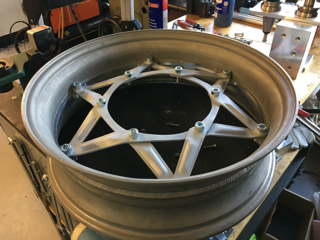
In order to create the sizes needed we sourced a rear VF1000R rim to provide the correct rim for the front along with the required struts/spokes. An additional wheel was sourced to provide the struts for the rear wheel. Both wheels needed custom hubs to be designed and manufactured and a custom 5″ rear rim was also required to be manufactured.

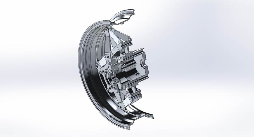
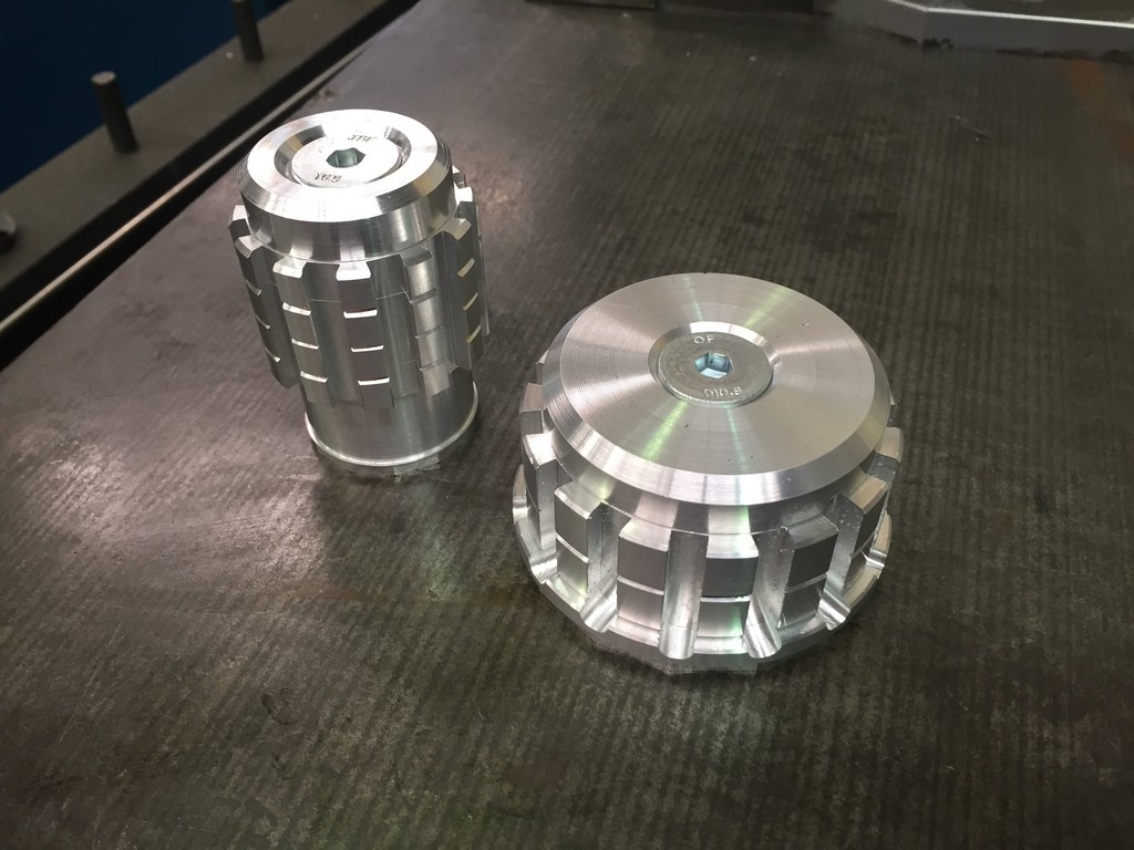
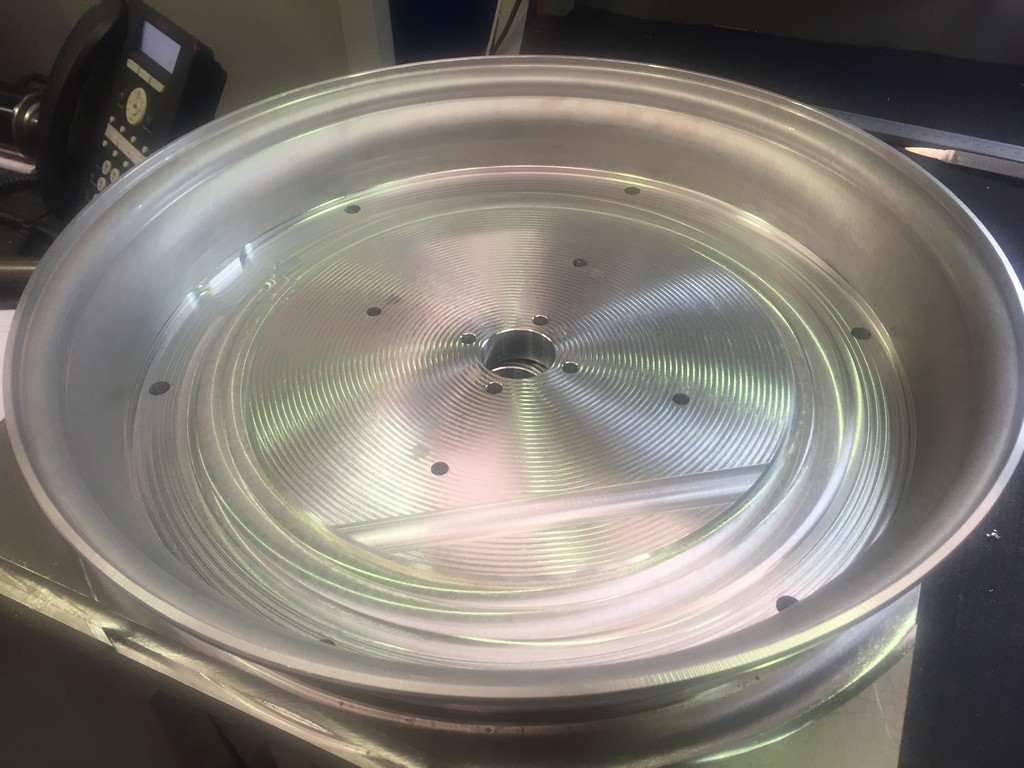
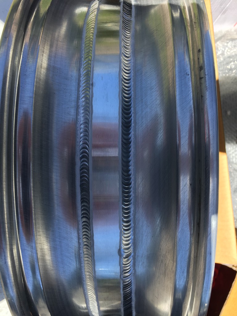
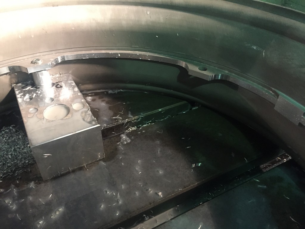
The rear rim halves were supplied to our specification by a local wheel spinning company. The halves were then fitted up a to machined centre section and welded together. The centre section was then machined to the final profile featuring all the mounting points and valve stem hole. The rims were then sent away for heat treatment and truing.


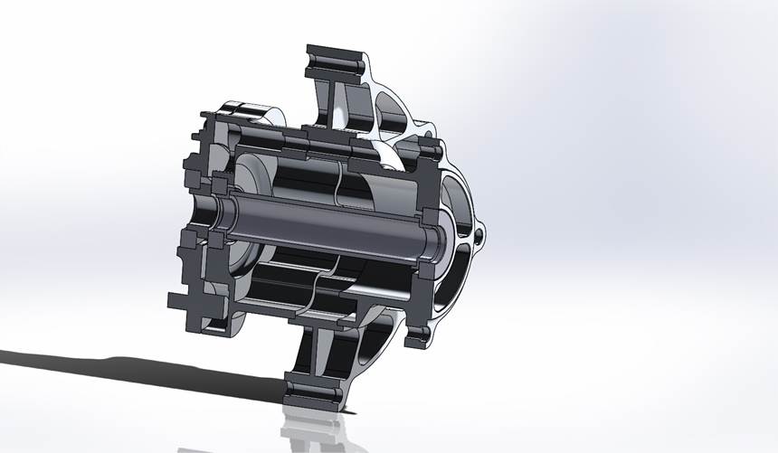
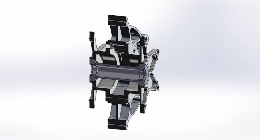
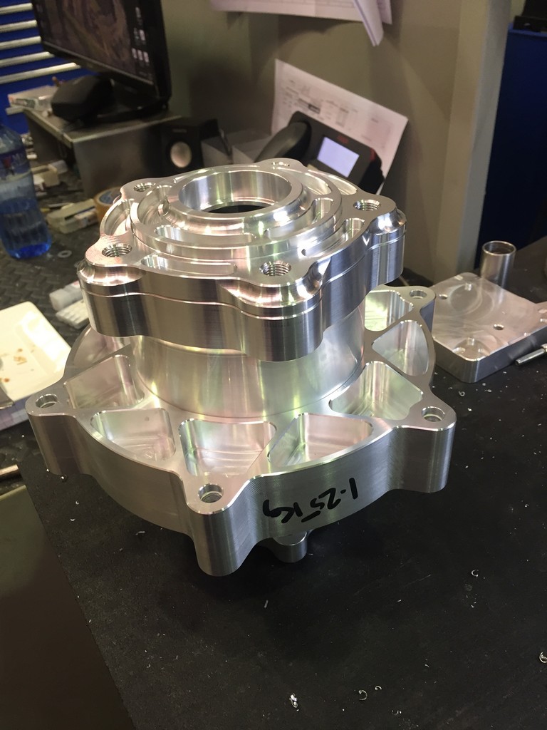
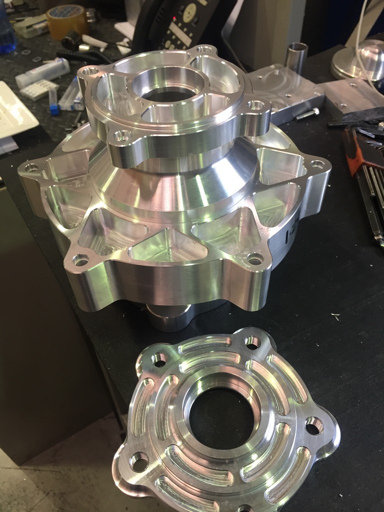
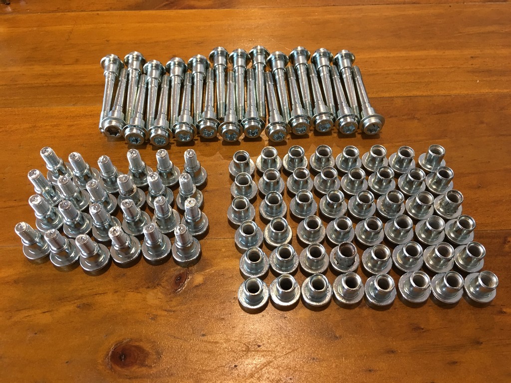
In the meantime the front and rear hubs, cush drives, sprocket carriers, disc rotor carriers and centres were machined.


Period correct disc rotors were supplied by a brake manufacturer from our drawings and specifications.

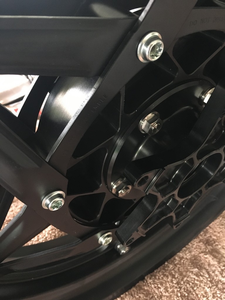
Upon completion of the fabrication of all the parts a trail fit up was undertaken and when we were happy with the outcome the parts were sent off for refinishing in a combination of anodising, replating painting and polishing.


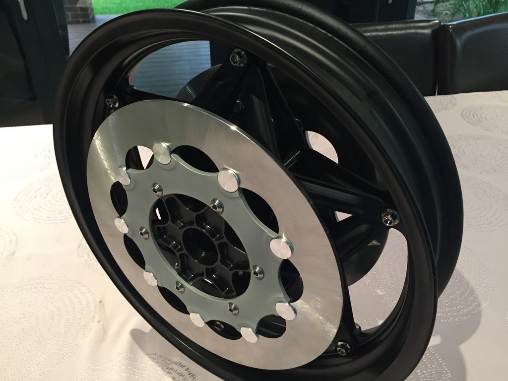
Once all the parts had been refinished they were assembled and declared ready to roll.


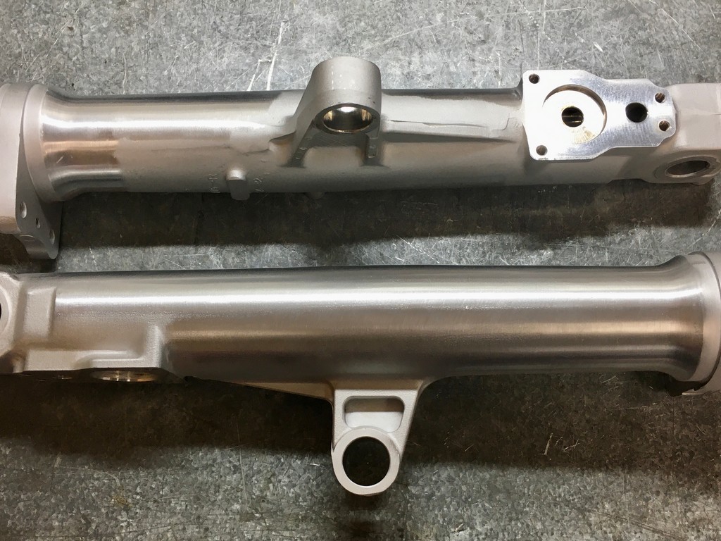
The FWS1000 used 41.3mm Showa forks. They’re a distinctive looking fork due to the external fluid tubes, adjustments and anti-dive features etc.

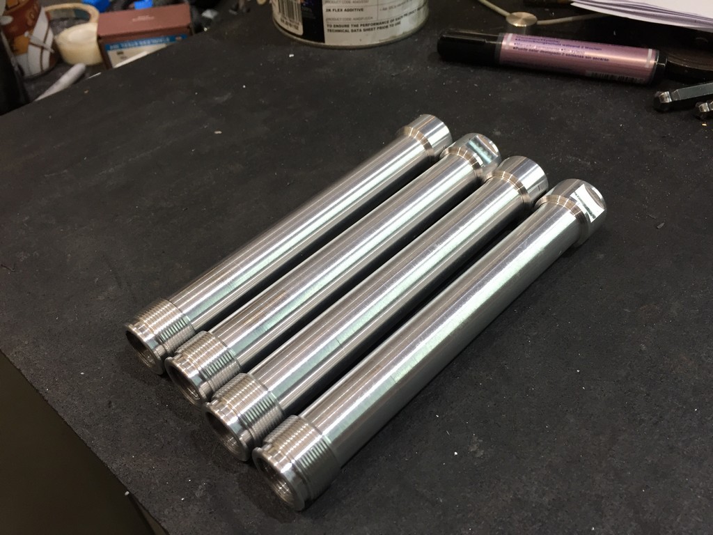
The regulations for the racing class we’re entering requires that the forks be no bigger than 41mm in diameter and that the external appearance of the forks are to be visually comaptible with the era represented however, internal modifications are free. The original Showas are not the type of part you can find at swap meets or on eBay so we had to find a way of making a set of forks that looked somewhat similar. After some searching we settled on the Goldwing GL1500 fork. They were 41mm and the bottom sliders featured similar mounting lugs for the anti-dive layout. The tubes on the GL1500 are waisted near the top triple clamp area which is unsuitable for the clip-on handlebars we ‘re using so we adapted CBR600F2 tubes for that role.
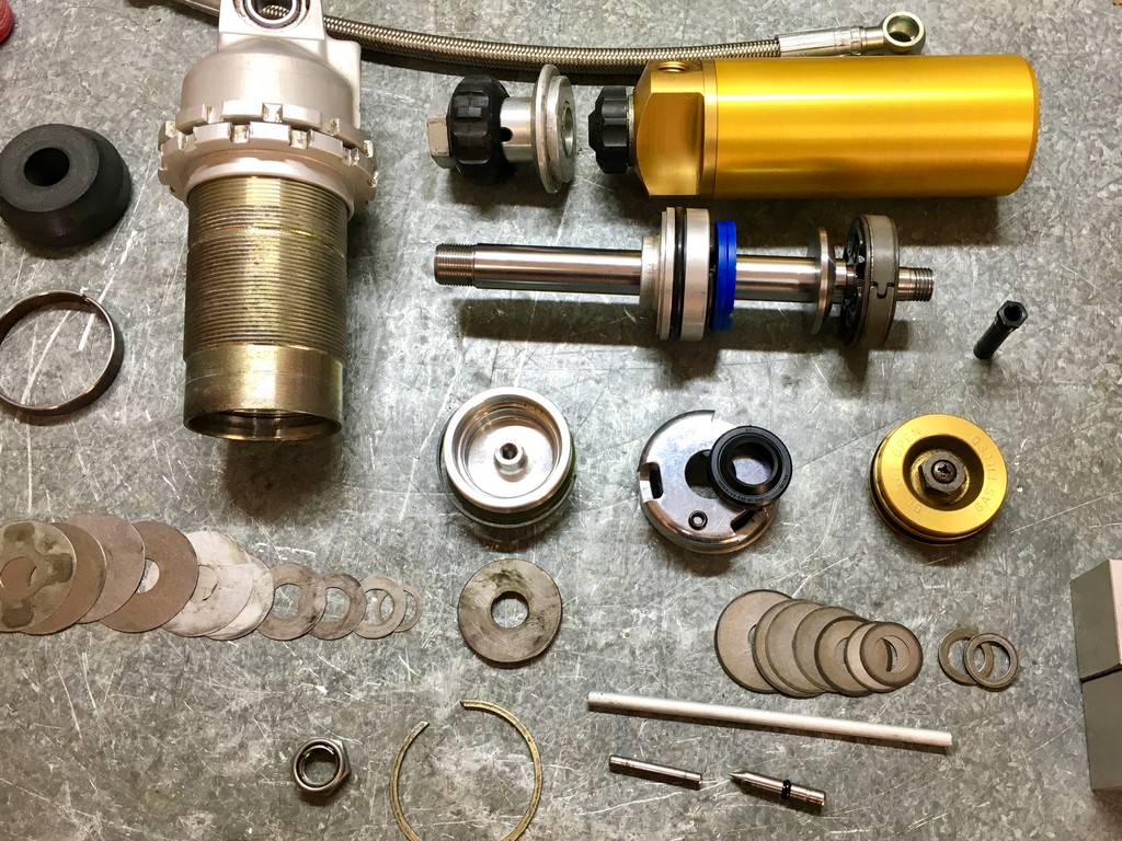
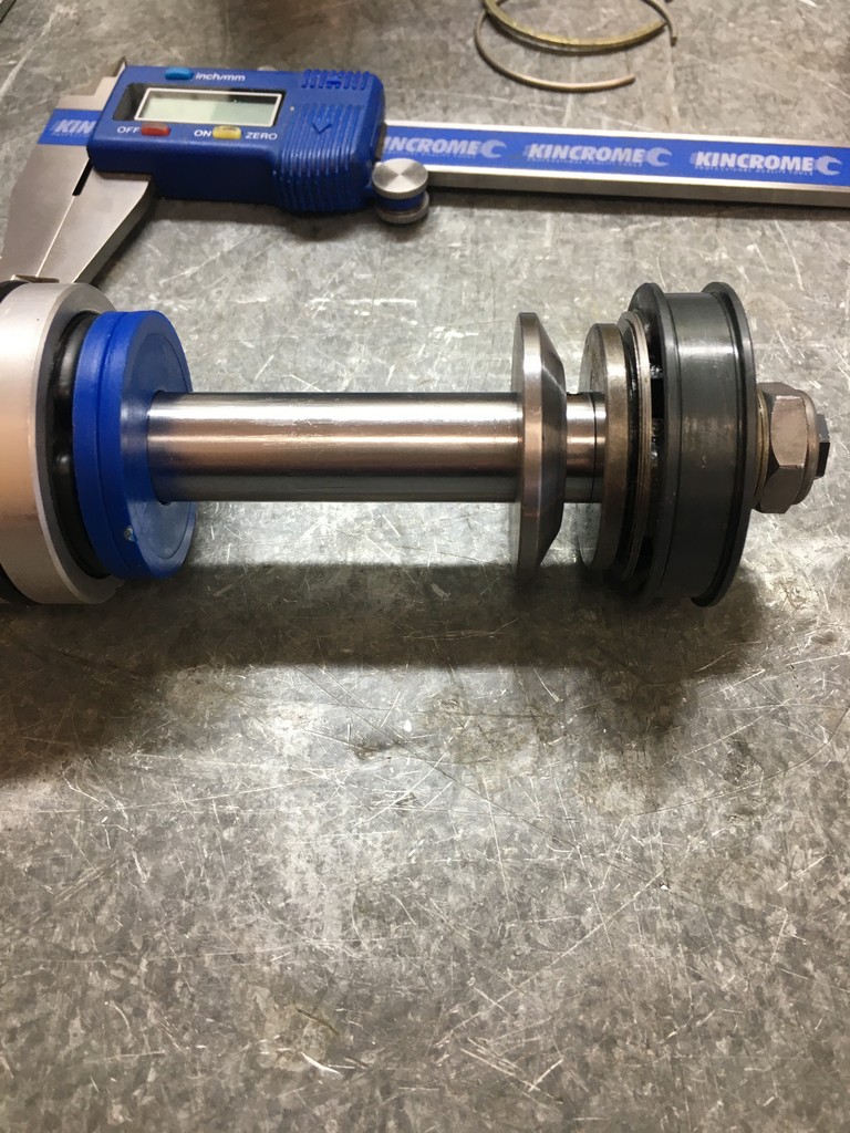
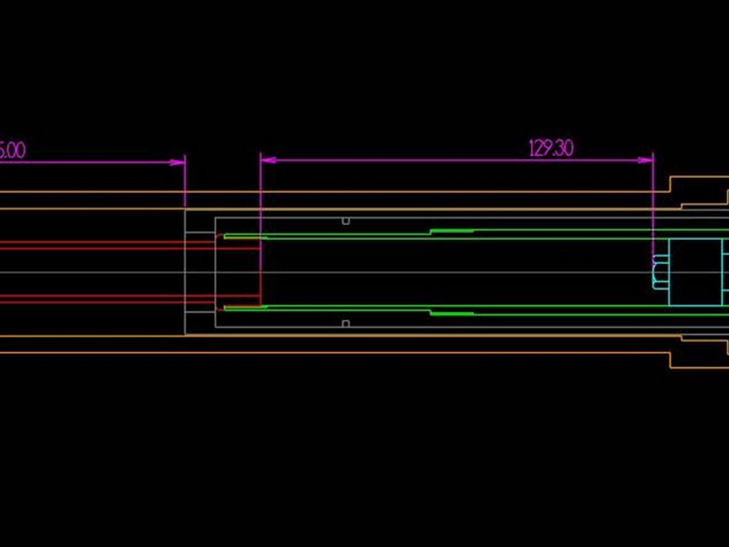
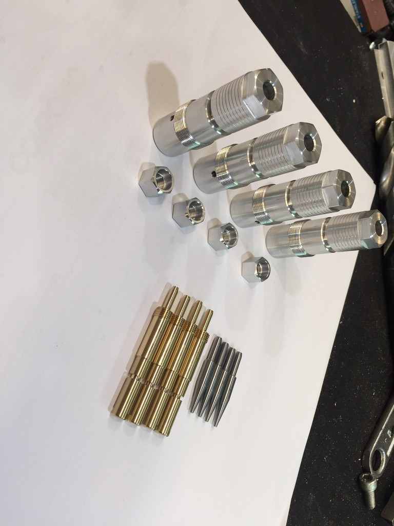
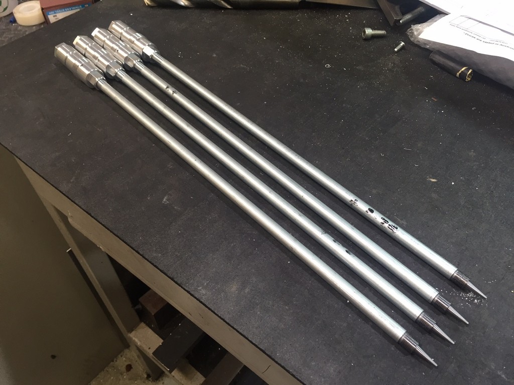
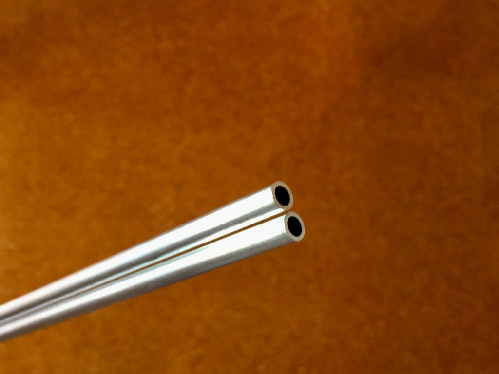
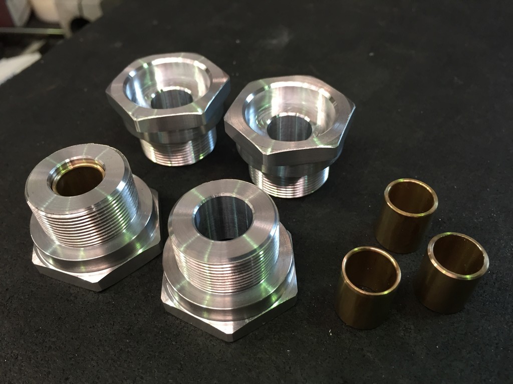
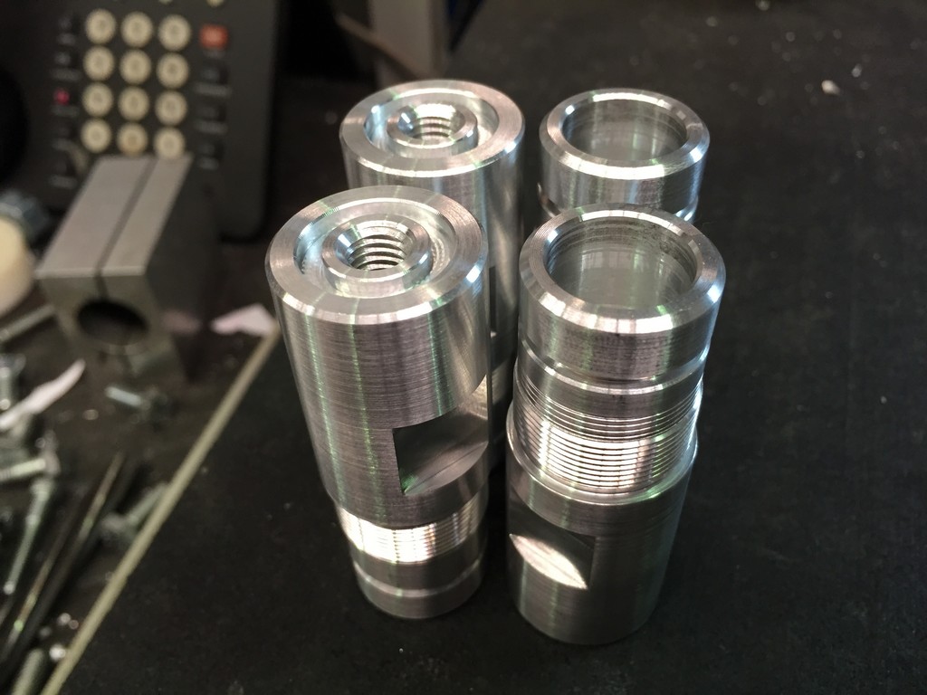
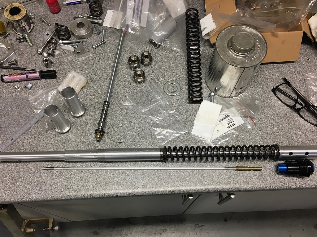
Due to the hybrid nature of these forks there are no aftermarket cartridge solutions available so we had to design our own cartridges using Ohlins NIX22 pistons. While we were at it we also incorporated a top out spring system. The cartridge tubes, damper and adjustment rods, needles, piston holders, fork caps and preload adjusters were all custom made to adapt to the Goldwing fork bottoms, CBR600F2 tubes and Ohlins NIX22 pistons. A special shout out goes to Laurie Smith from Suspension Smith https://www.facebook.com/Suspensionsmith for shimming and valving the forks.


For the rear we used a remote reservoir Ohlins shock absorber specified for a Honda CBR600F2 because the rear suspension has a similar motion ratio and travel. Final choice of spring and valving will have to be evaluated on the track. A longer lower extension was fabricated to enable the shock to fit through the rear swingarm.