

In my last post I mentioned how we were getting down to the last 5% of the build. I may have underestimated that figure. Getting things as ‘right’ as possible on this project has truly been a journey. A number of small but important details needed to be attended to. We’re getting right down to the wire now.
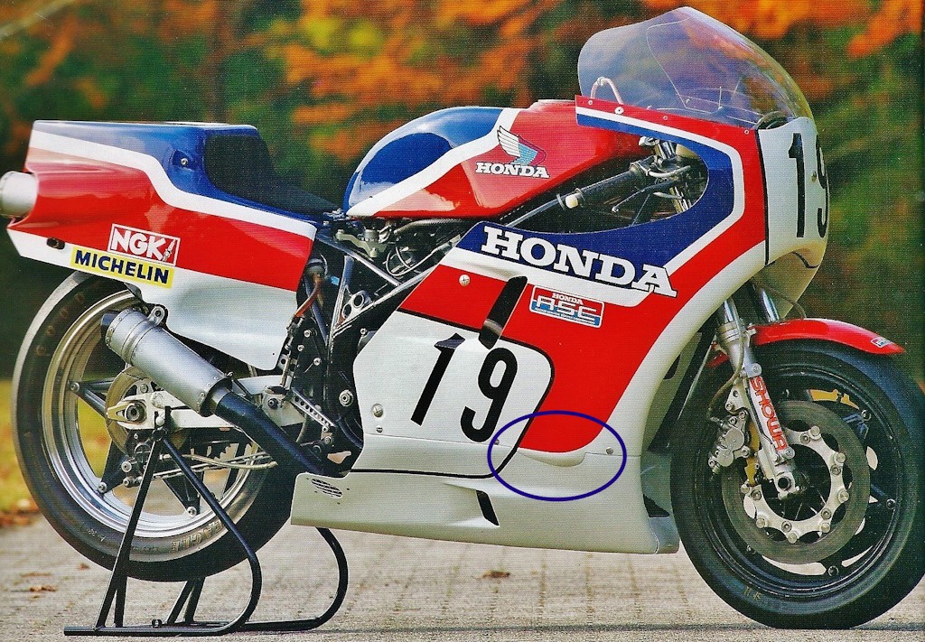
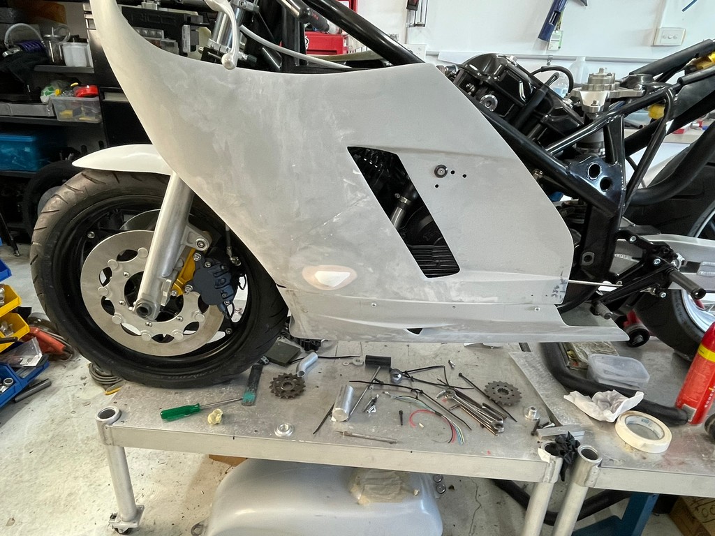
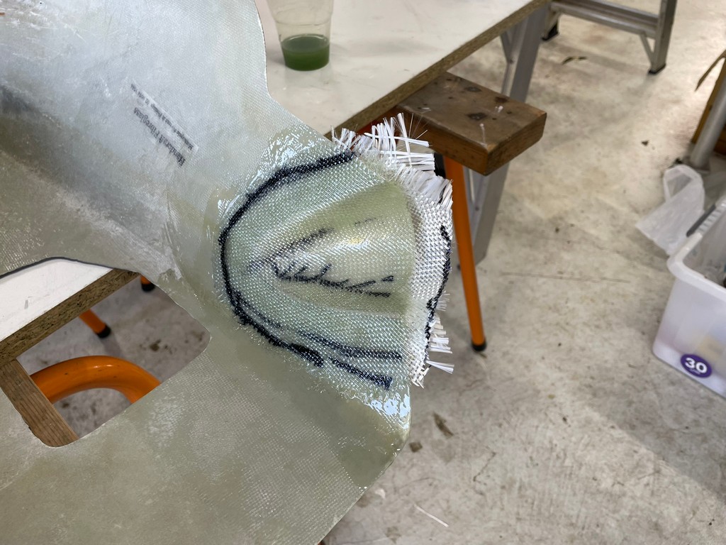
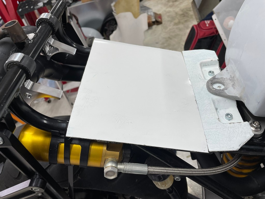
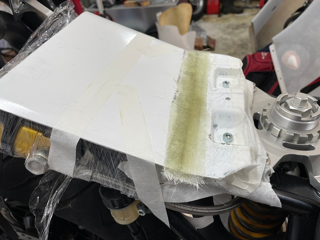
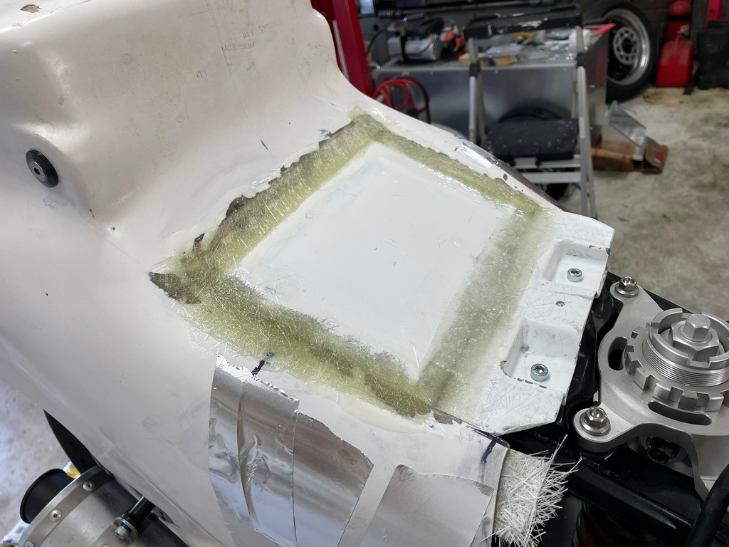
Having never seen a real FWS1000 in the flesh we were always curious about the reason for the aero bumps or humps on the fairing sides where it meets the belly-pan. We found out when the fairing was offered up to the chassis for the first time with the radiator installed. The lowest outboard edges of the radiator are wider than the fairing at that point and fouled on the fairing. In some way this gives us comfort that the form and dimensions of our model is quite true to the original.
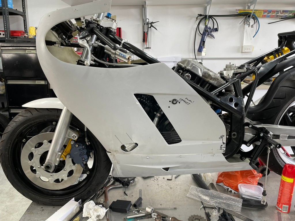
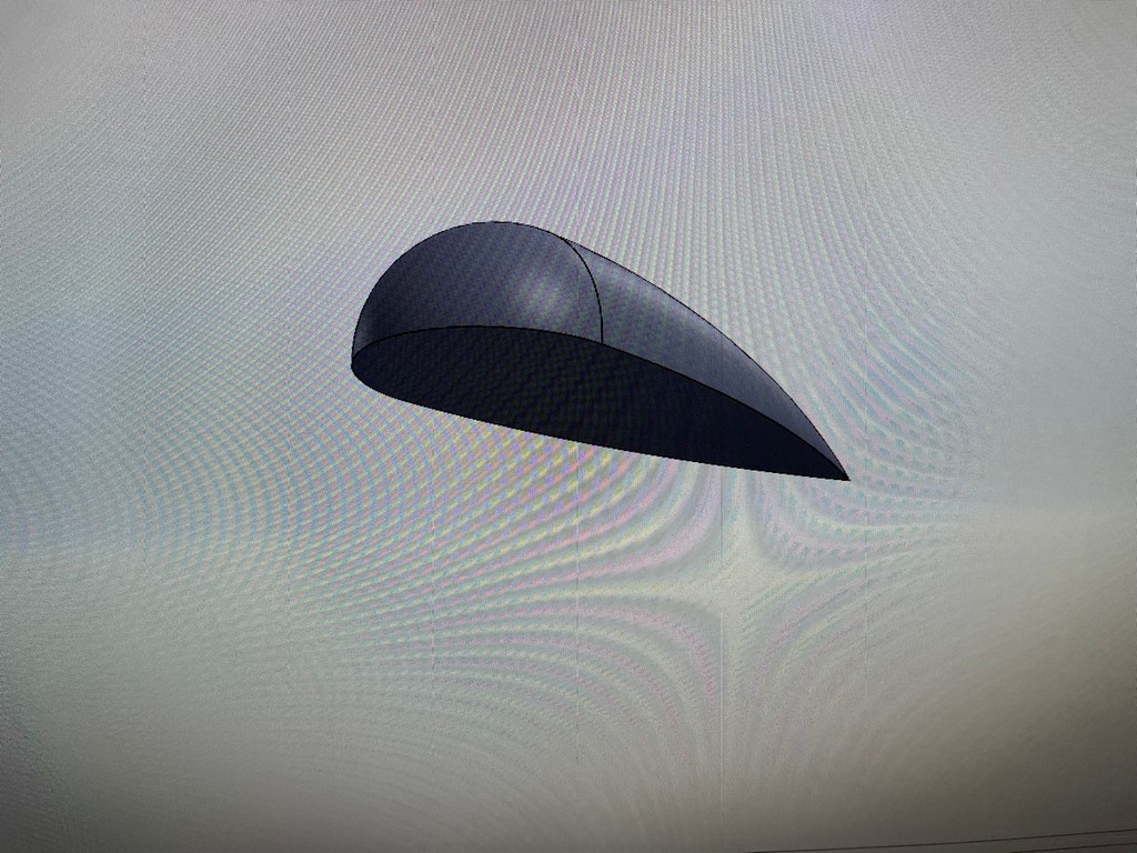
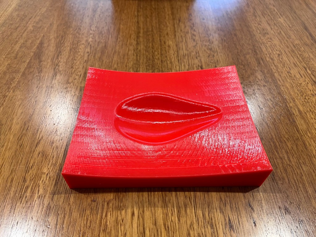
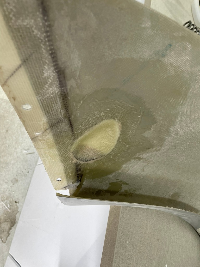
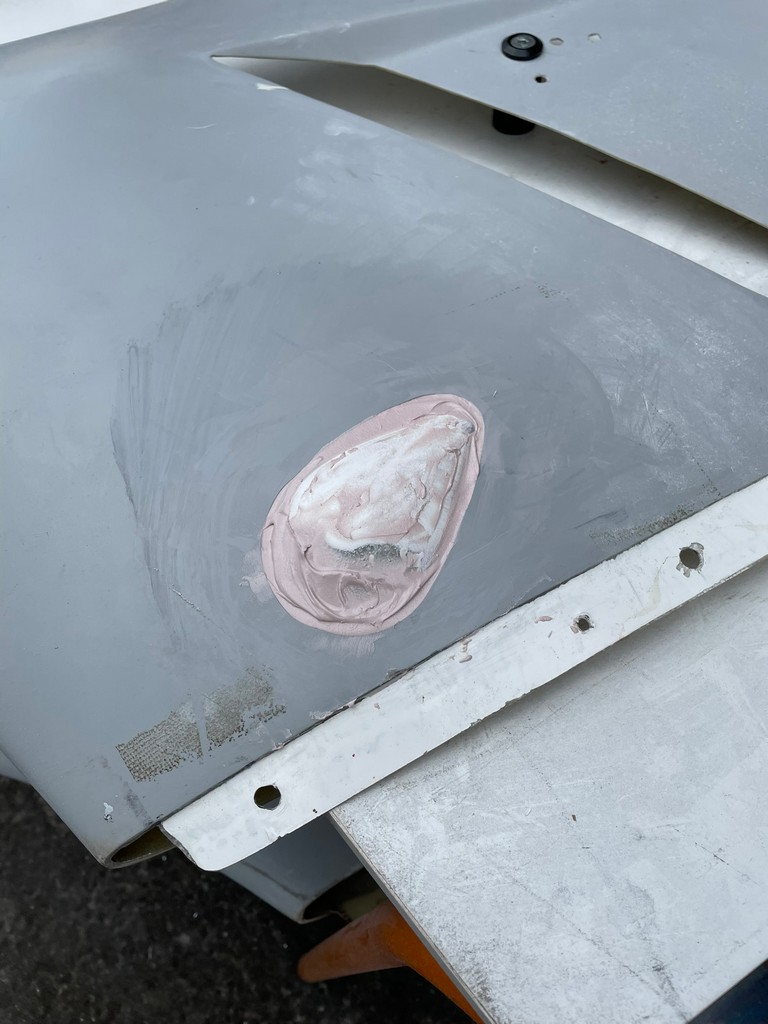
To correct this issue we CAD modelled a hump and 3D printed a pattern to form a mould. A laminate was taken from the mould which was then glued to the fairing and blended in. We’ll keep it this way whilst testing the bike. Some time down the track the mould for the fairing will be modified to incorporate the hump.
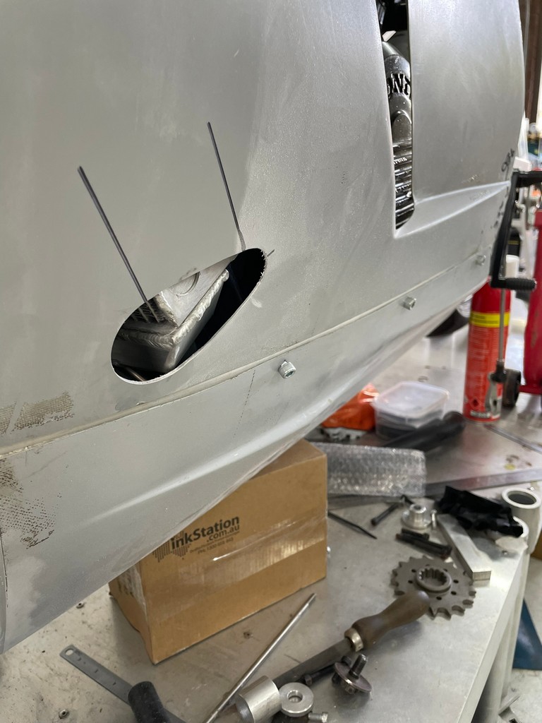
A similar scenario presented itself where the exhaust exited from the front cylinders.


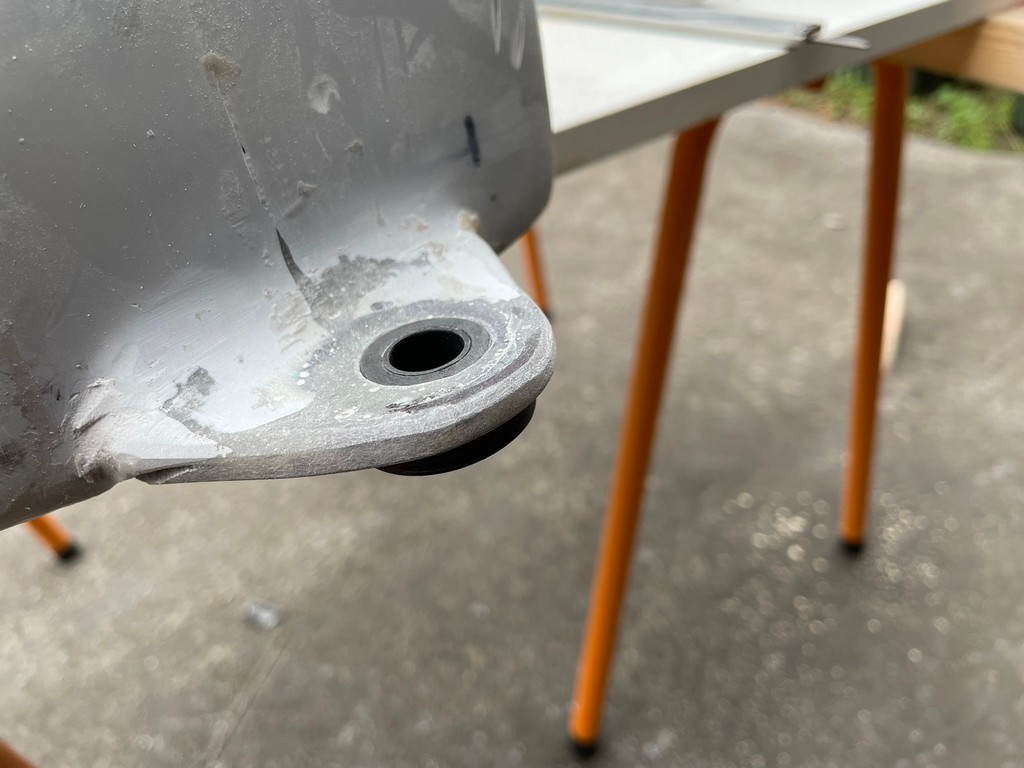
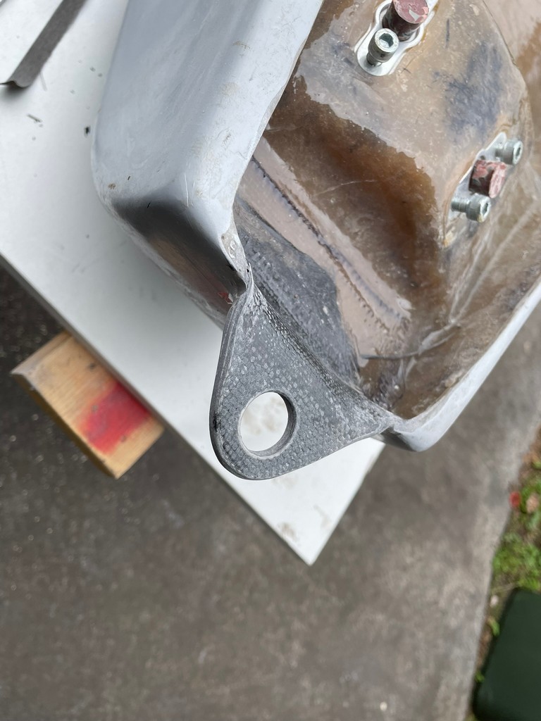
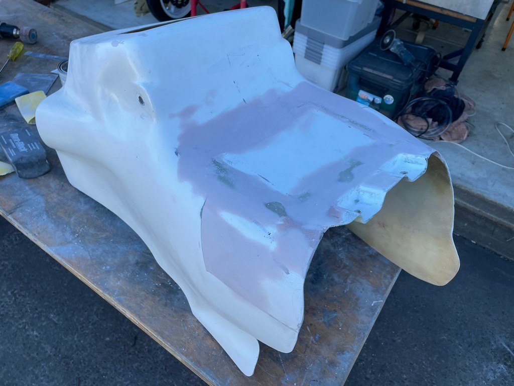
It might be a case of being too picky about the details but we’ve come this far to let some issues slip through and spoil the presentation of the bike. One aspect we weren’t happy with was how the tank sat on the frame rails so the rear mount needed to be adjusted to get it just right.


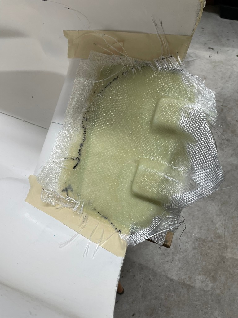
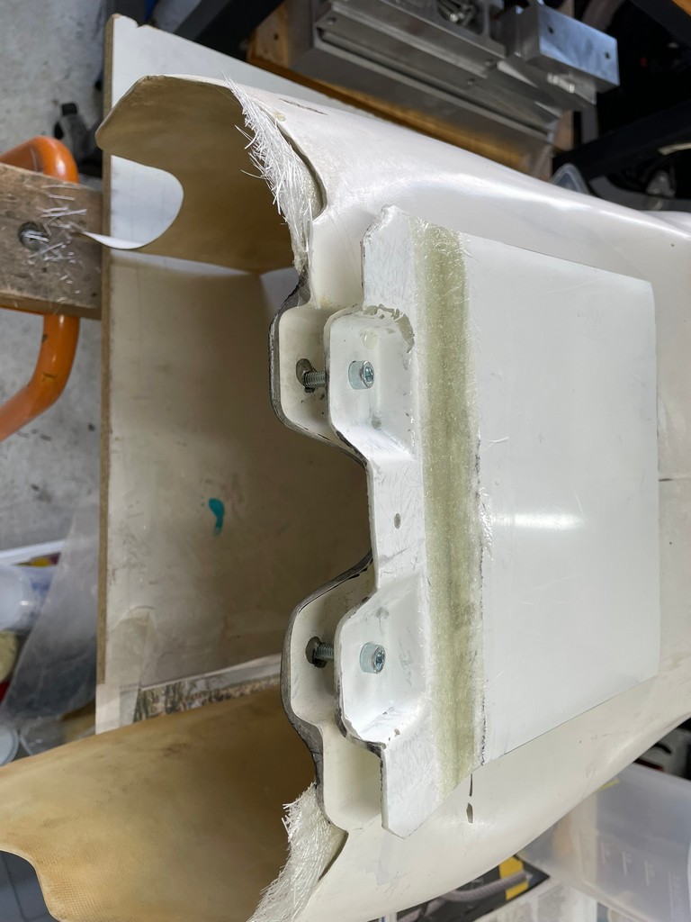
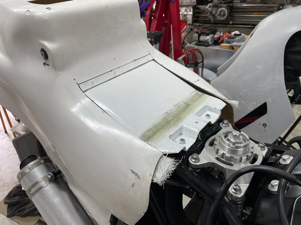
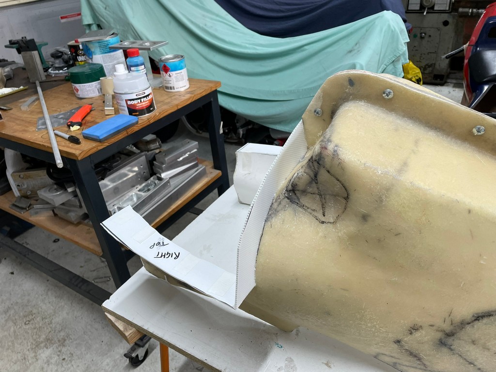
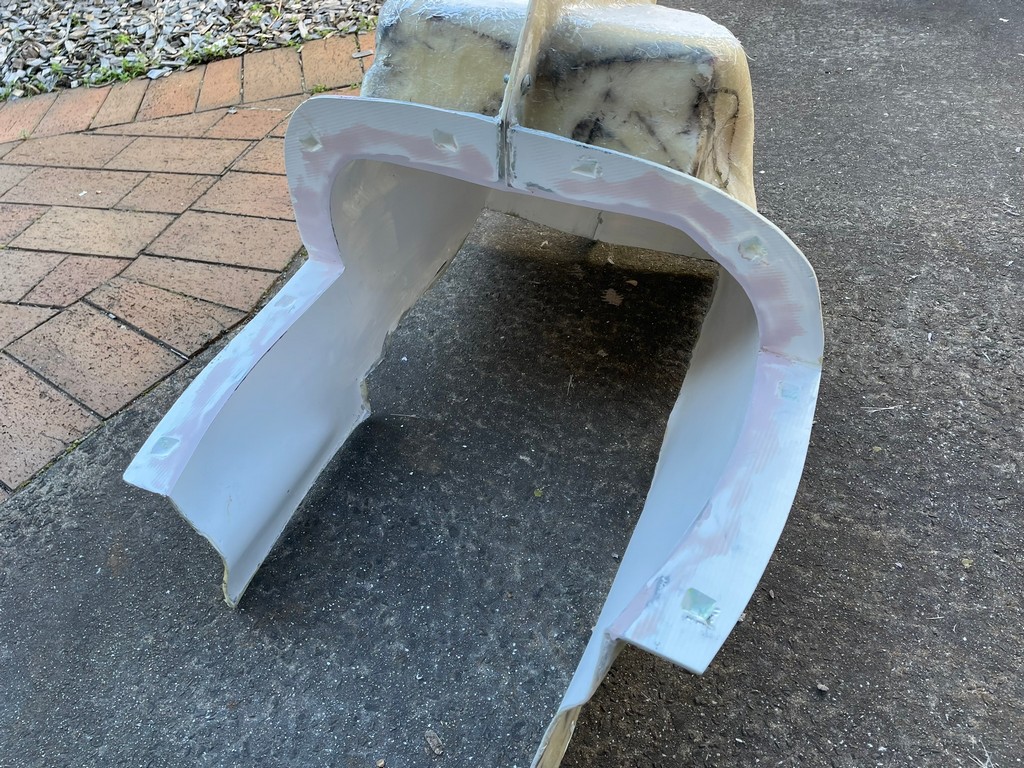
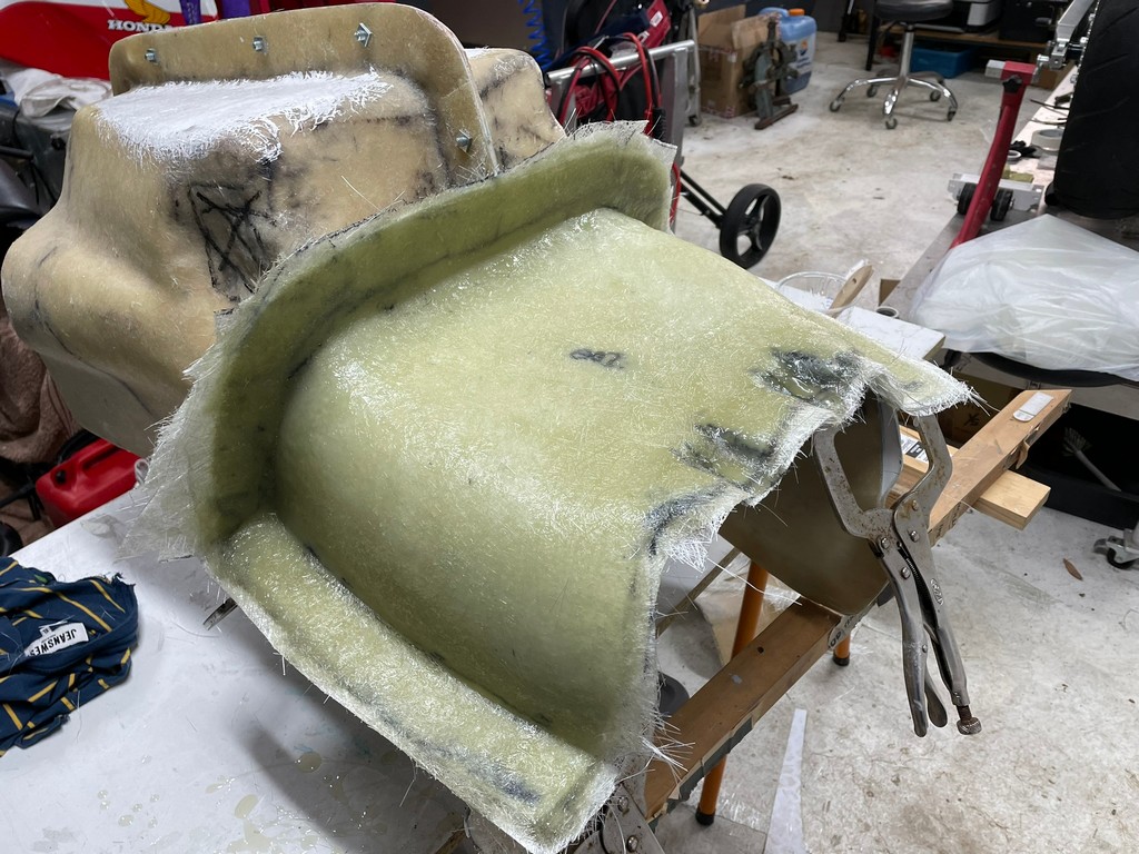
A consequence of doing things in an unorthodox order perhaps, presented itself with how the tailpiece/seat unit sat on the chassis sub frame. We modelled and fabricated the seat before fabricating the frame. This resulted in a gap between the two parts and thus was not structurally sound. We could’ve used packing to fill the gap but we weren’t satisfied with that approach. What was needed was for the seat unit to be reshaped/modified to correct the issue and a mould taken from the modified seat so that a new tailpiece/seat unit laminate will fit properly. This also ensures repeatability for future parts.

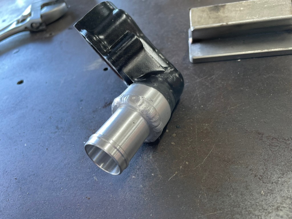
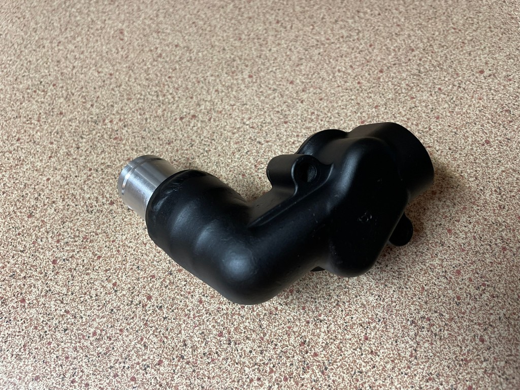
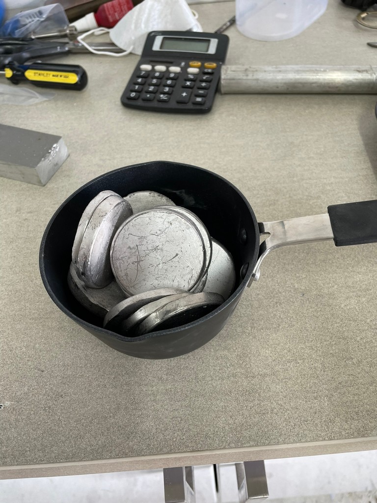
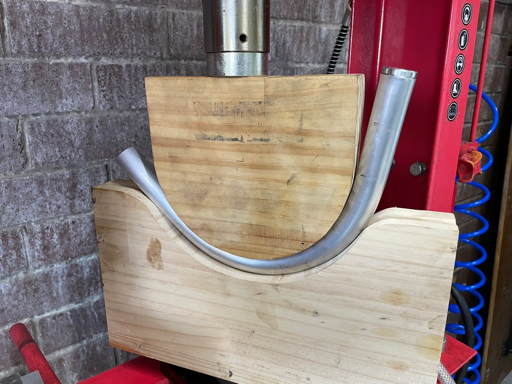
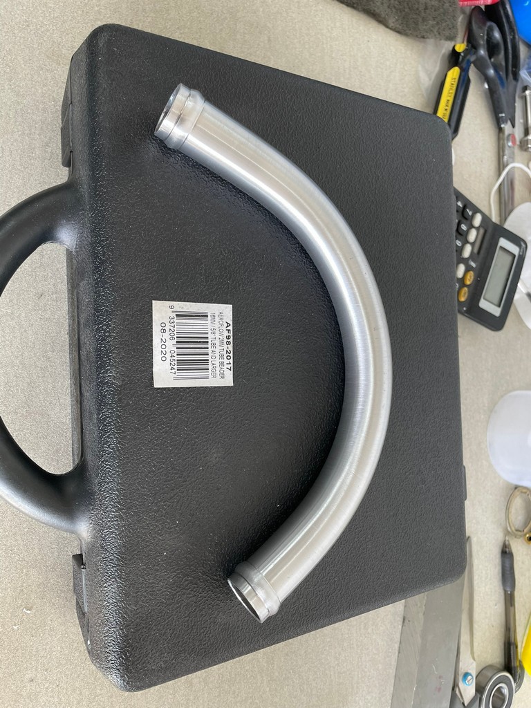
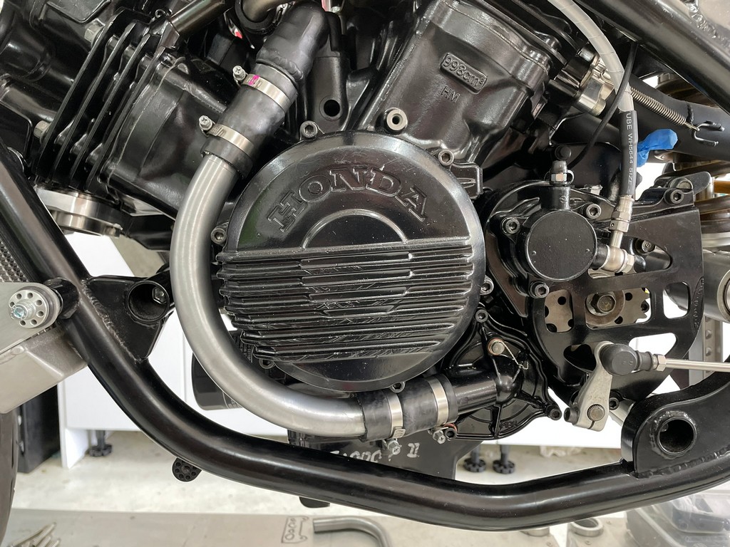
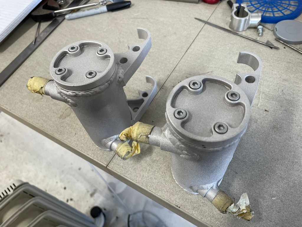
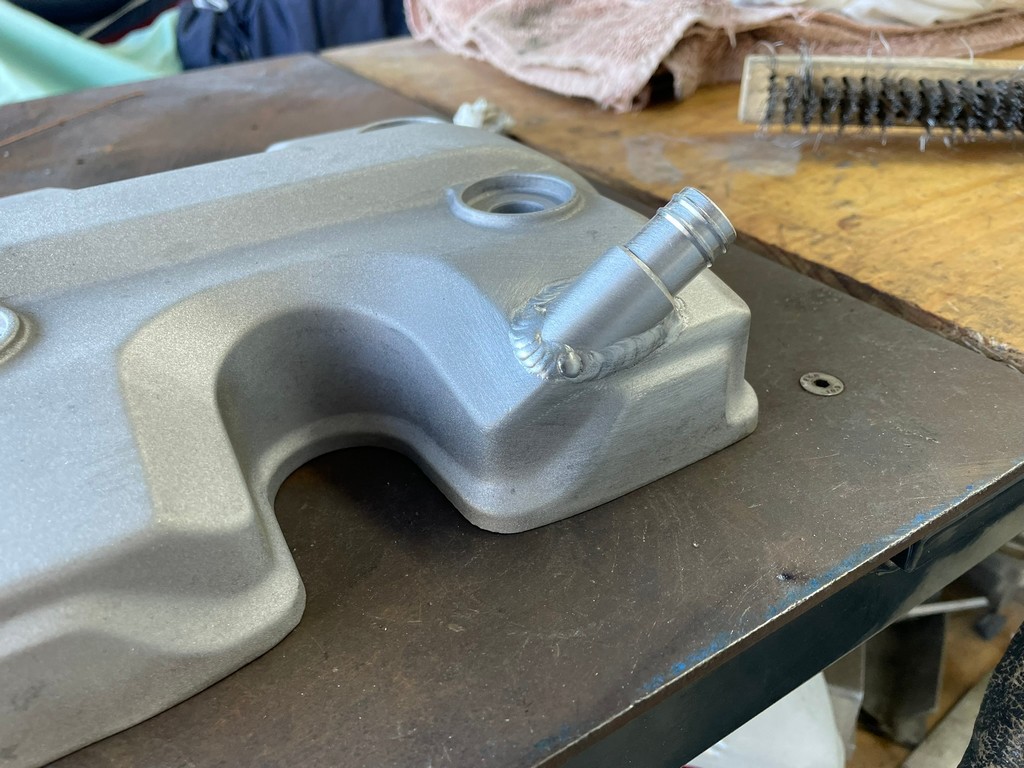
The stock Honda VF1000 rigid coolant pipe feeding the engine from the water pump wouldn’t fit our chassis so a custom pipe needed to be fabricated. Bending a short aluminium tube over a large radius with conventional benders wasn’t available to us so we used a variation of the sand filled method by using low melt temp alloy instead to keep the pipe from collapsing whilst it was being formed over a wooden mandrel. Once the bending was finished the alloy filler was melted out. The stock pipe adapter then had to be modified to suit.
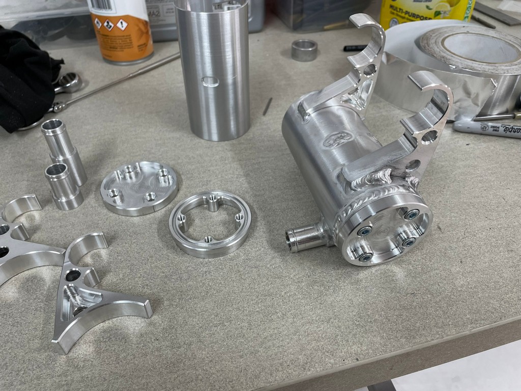
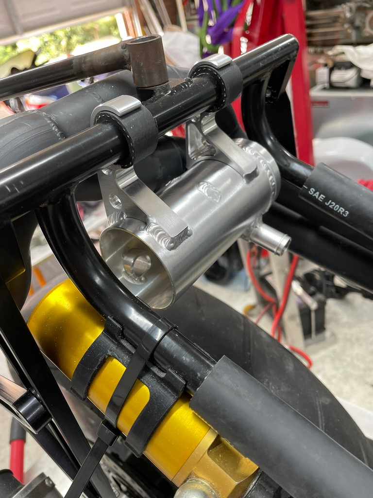
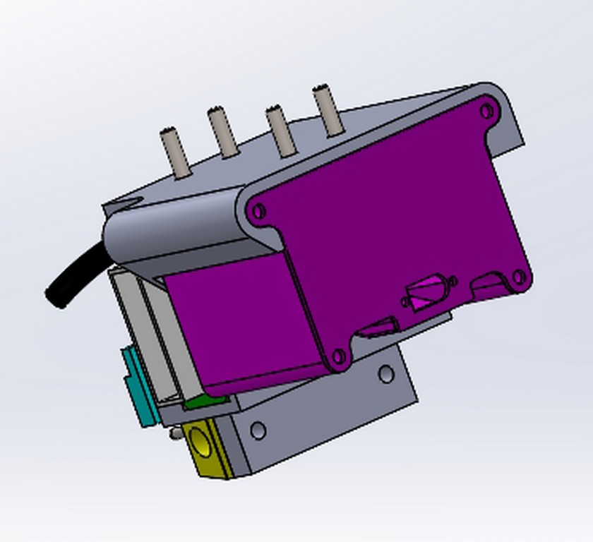
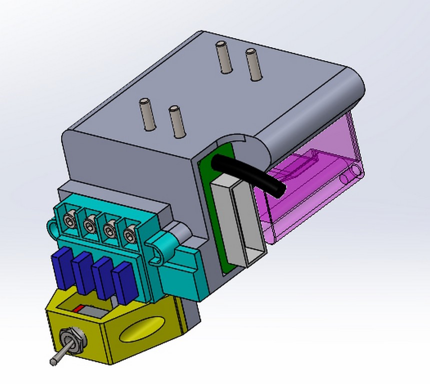
A custom breather tank with internal reed valve was then fabricated and fitted.


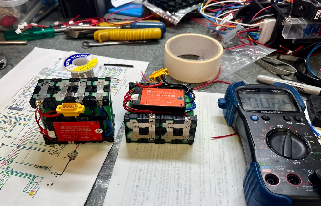
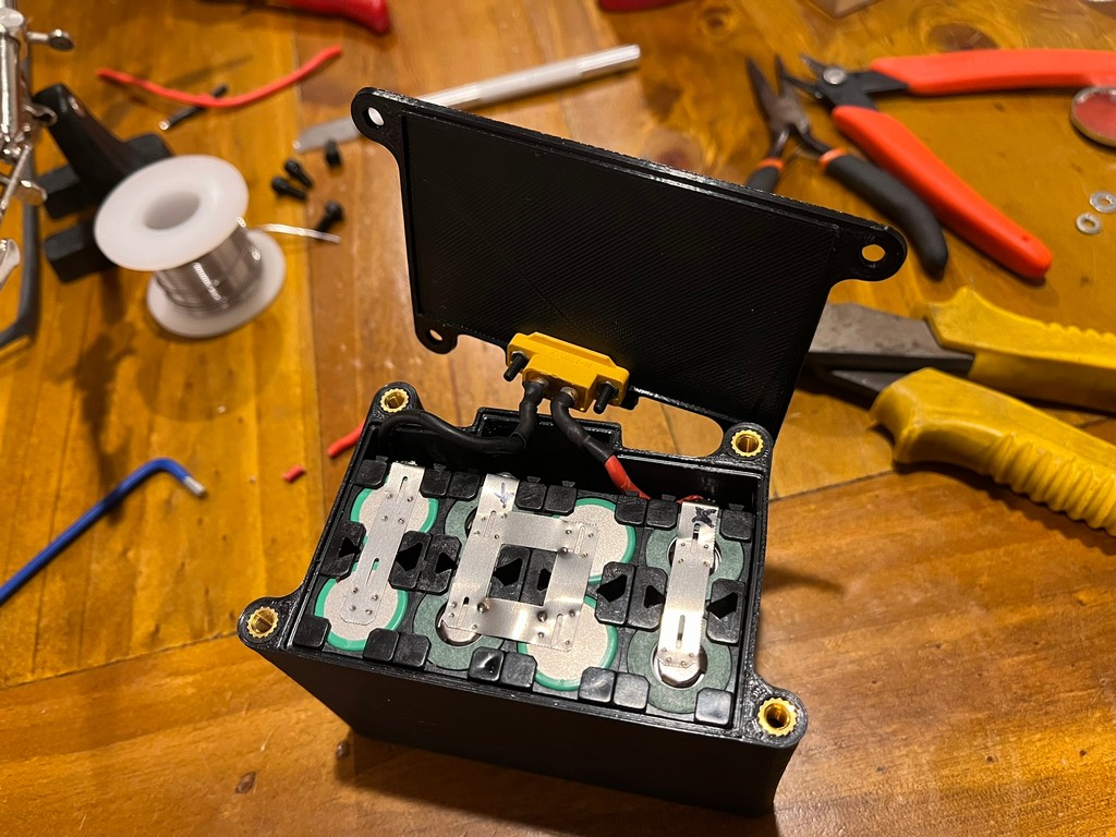
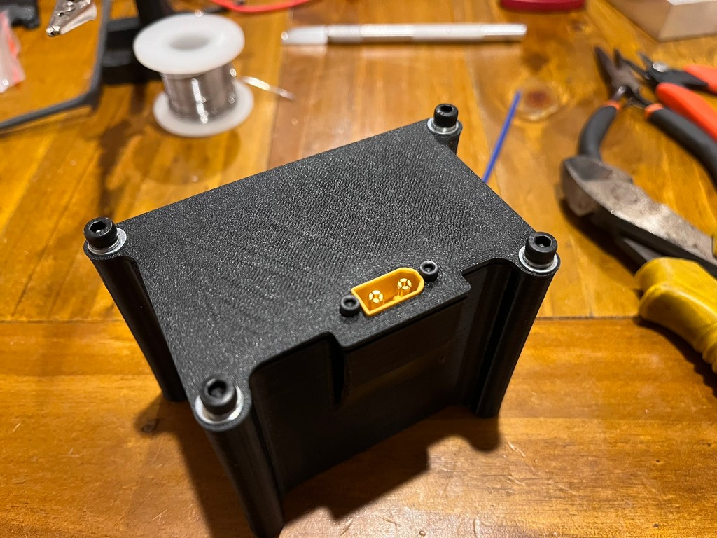
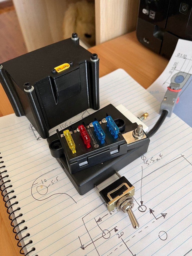
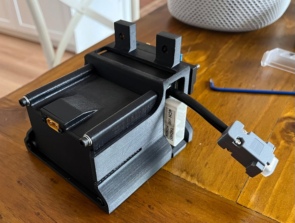
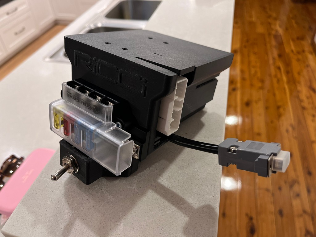
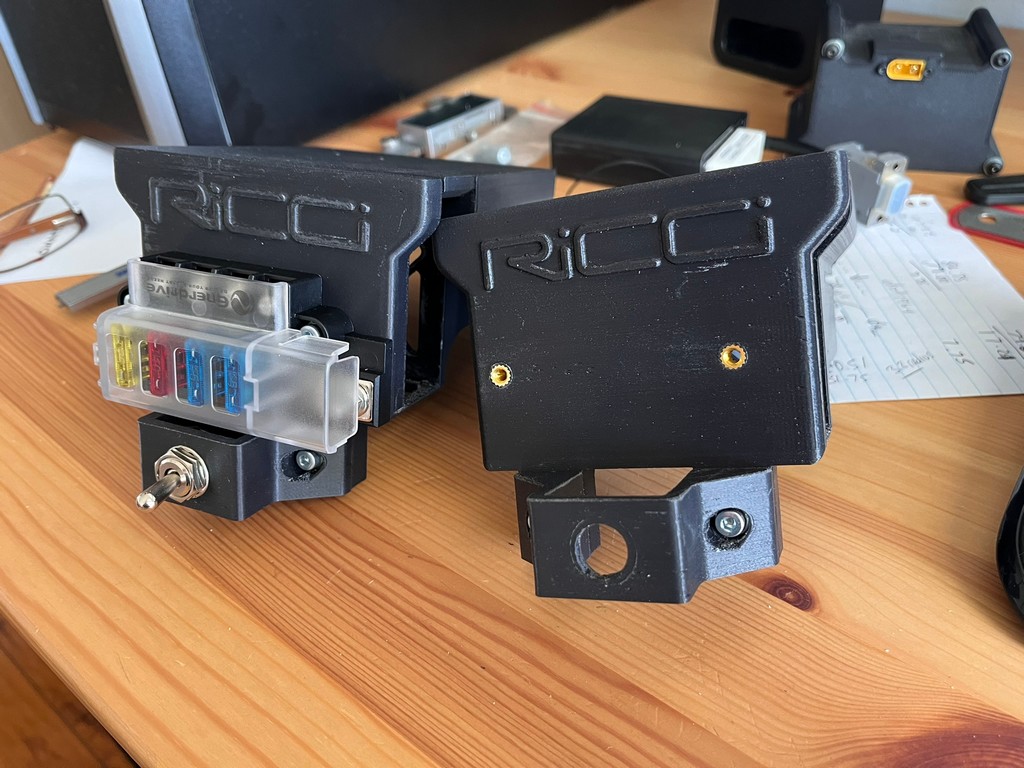
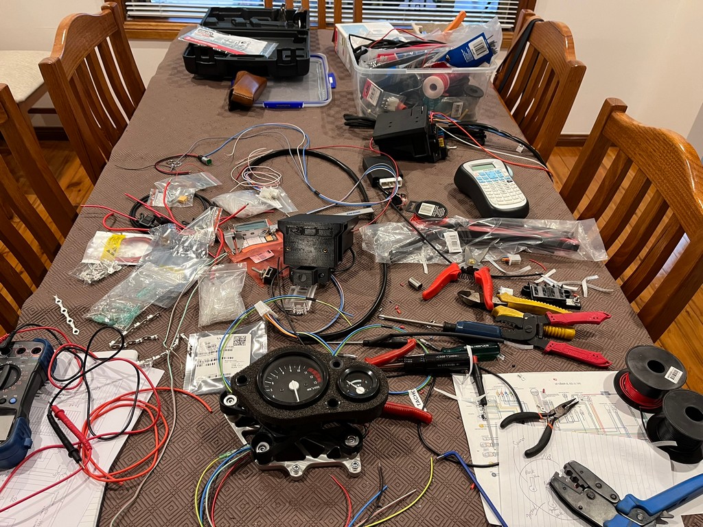
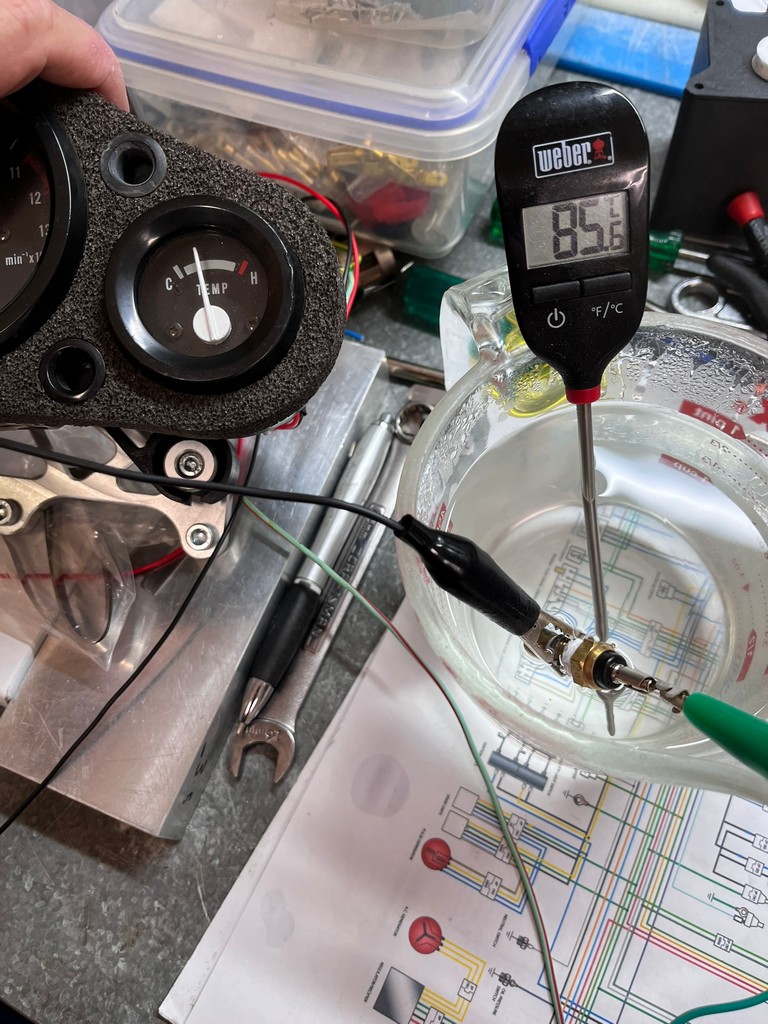
The electrical system and harness was manufactured with a custom lithium battery setup and a 3D printed mounting to house the battery, ignition box, fuses and main switch underneath the instruments.


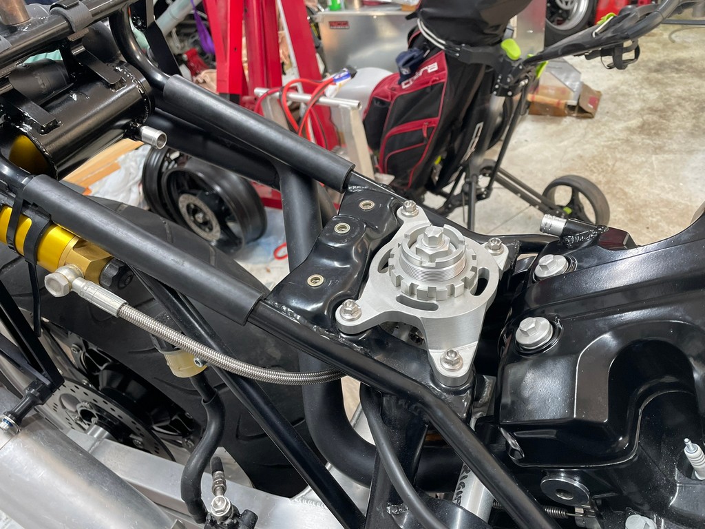
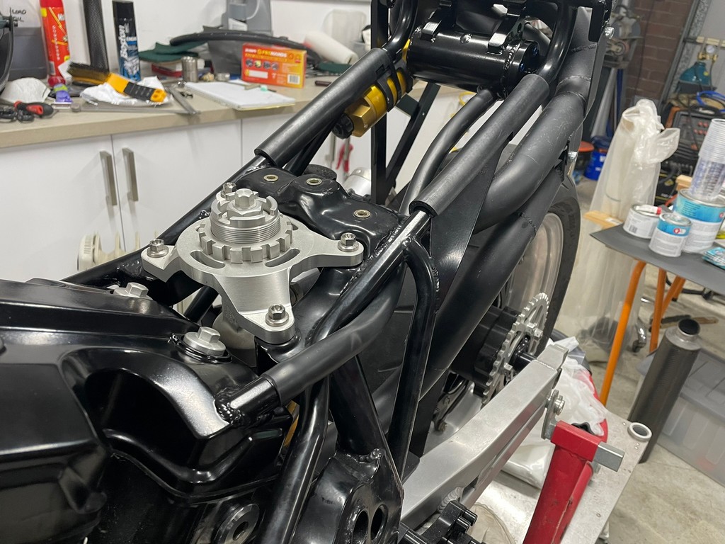
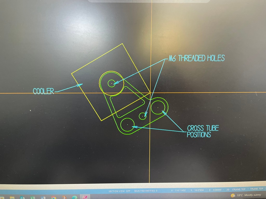
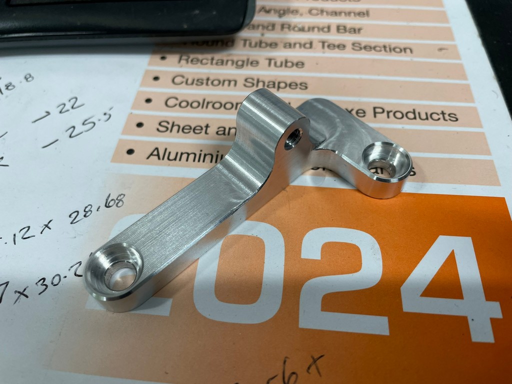
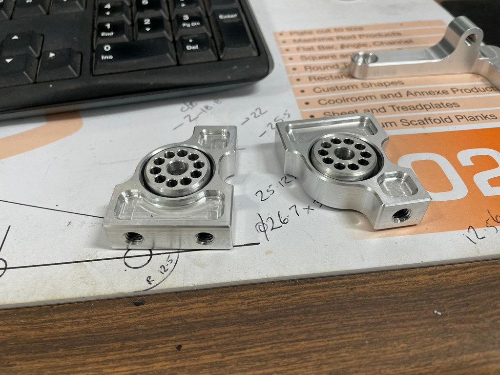
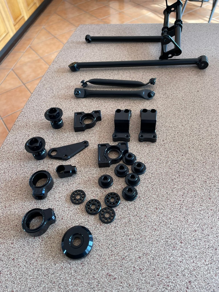
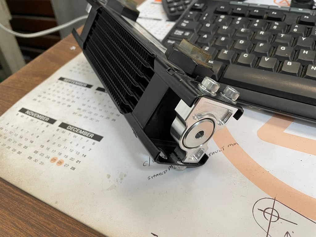
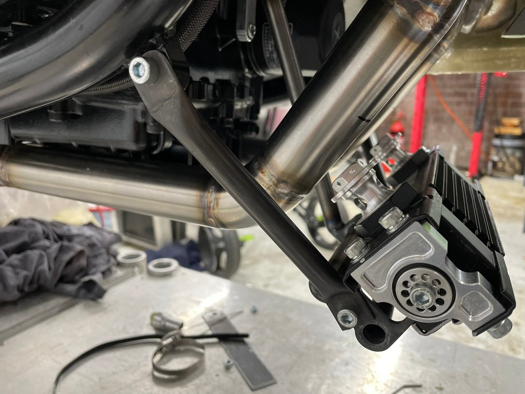
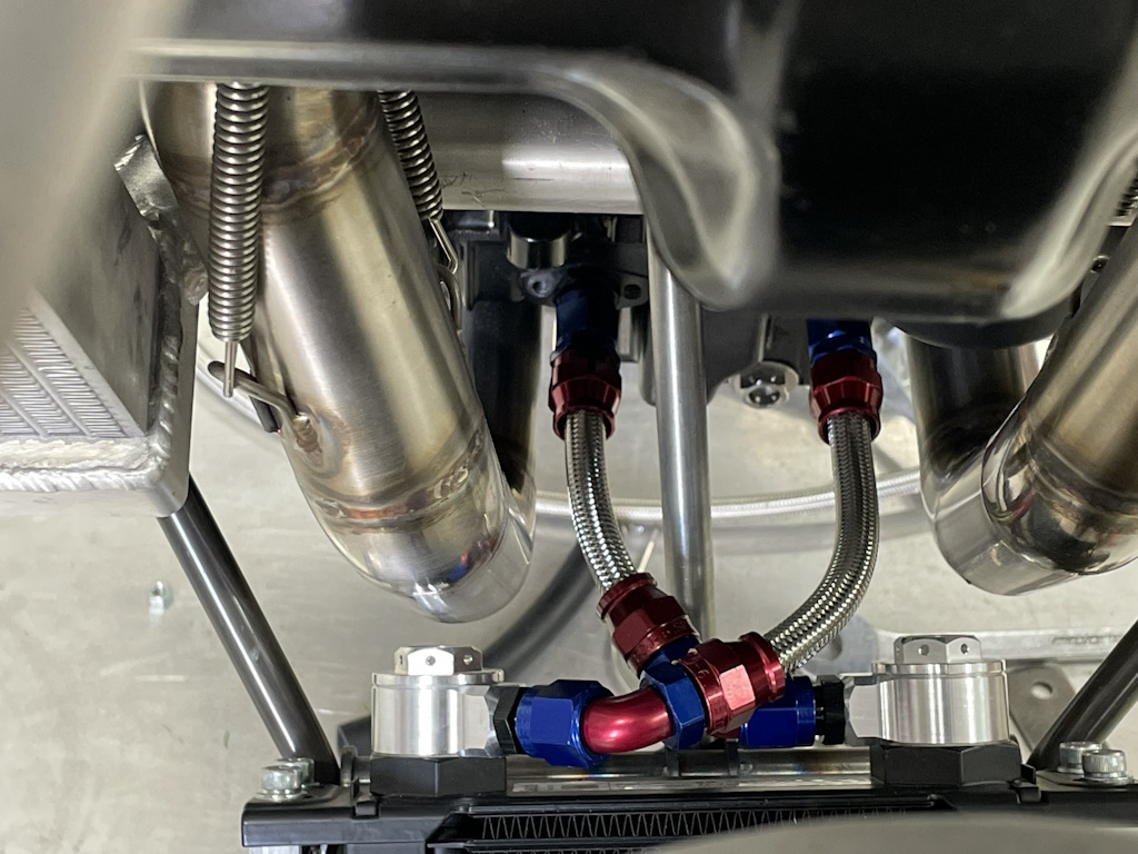
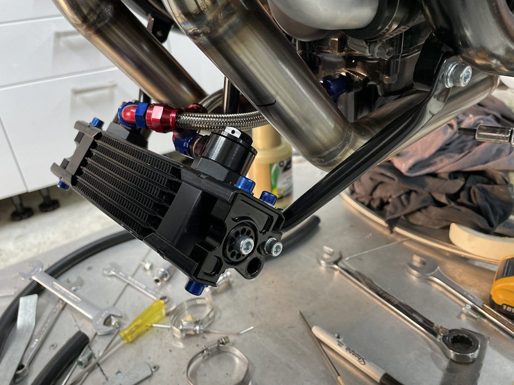
The location of the oil cooler is an iconic feature of the FWS1000 V4 and the RS models that followed it. I assume this was due to there being nowhere else to put the thing. Space is at an absolute premium on this tiny bike. Lots of small aluminum pieces and other brackets needed to be designed and manufactured for this mounting system. The cooler isn’t as big as we’d like but there just wasn’t enough room. Some appropriate modification of the belly-can maybe on the horizon but we’re so close to starting the engine on this thing to worry about that for now.


Fingers crossed that the next post will be all about how good the engine sounds!

Hi guys
<
div>Fabulous work and detail, can’t wait to see and hear
LikeLike
Thanks Dave.
LikeLike
Great work Don. I can’t imagine how many hours you guys have in this now.
LikeLiked by 1 person
I don’t want to think about that!
LikeLike
I head down to the shed for a couple of hours and my wife hunts me out with a vengeance. You are a lucky man from that respect.
LikeLike